Image processing techniques

a technology of image processing and image, applied in the field of graphic processing, can solve the problems of affecting the effect of character's shadow and the affecting the effect of character's shadow and corresponding light-view depth value, and relatively expensive vertex processing used to render the character's triangle,

Inactive Publication Date: 2011-06-16
INTEL CORP
View PDF13 Cites 10 Cited by
  • Summary
  • Abstract
  • Description
  • Claims
  • Application Information

AI Technical Summary

Problems solved by technology

However, the character's shadow and corresponding light-view depth values would not be relevant for this scene.
Relatively expensive vertex processing is used to render the character's t

Method used


Image

  • Image processing techniques
  • Image processing techniques
  • Image processing techniques

Examples


Embodiment Construction

[0013]Reference throughout this specification to “one embodiment” or “an embodiment” means that a particular feature, structure, or characteristic described in connection with the embodiment is included in at least one embodiment of the present invention. Thus, the appearances of the phrase “in one embodiment” or “an embodiment” in various places throughout this specification are not necessarily all referring to the same embodiment. Furthermore, the particular features, structures, or characteristics may be combined in one or more embodiments.

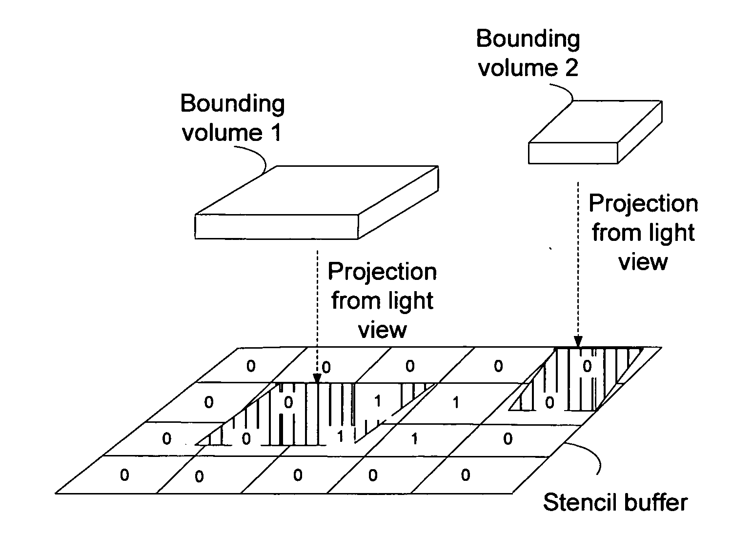
[0014]Various embodiments enable hierarchical culling during shadow generation by using a stencil buffer generated from a light view of the eye-view depth buffer. The stencil buffer may be generated by projecting depth values in a standard plane of a camera view onto a light-view image plane. The stencil buffer is from a light view and indicates points or regions in the eye view that could potentially be in shadow. If nothing is between a point...


PUM


Abstract

Hierarchical culling can be used during shadow generation by using a stencil buffer generated from a light view of the eye-view depth buffer. The stencil buffer indicates which regions visible from an eye-view are also visible from a light view. A pixel shader can determine if any object could cast a shadow by comparing a proxy geometry for the object with visible regions in the stencil buffer. If the proxy geometry does not cast any shadow on a visible region in the stencil buffer, then the object corresponding to the proxy geometry is excluded from a list of objects for which shadows are to be rendered.

Description

FIELD[0001]The subject matter disclosed herein relates generally to graphics processing, including the determination of which shadows to render.RELATED ART[0002]In image processing techniques, shadows are defined for unique objects on a screen. For example, G. Johnson, W. Mark, and C. Burns, “The Irregular Z-Buffer and its Application to Shadow Mapping,” University of Texas at Austin (April 2009) (available at http: / / www.cs.utexas.edu / ftp / pub / techreports / tr04-09.pdf) describes classical techniques for conventional and irregular shadow mapping of a scene based on light view and eye / camera view depth buffers with respect to its FIG. 4 and accompanying text.[0003]From a light perspective, consider a scene in which a character is standing behind a wall. If the character is completely within the wall's shadow, the character's shadow does not have to be evaluated because the wall's shadow covers the area where the character's shadow would have been. Typically, in a graphics pipeline, all ...

Claims


Application Information

Patent Timeline
IPC IPC(8): G06T15/60G09G5/36
CPCG06T15/60G06T15/005G06T15/405
Inventor HUX, WILLIAM ALLENMCNABB, DOUG W.
Owner INTEL CORP
Why Eureka
Try Eureka