Boost Multilevel Inverter System

a multi-level inverter and booster technology, applied in the direction of dc-ac conversion without reversal, process and machine control, instruments, etc., can solve the problems of high breakdown voltage, high current limitation, and high cost of switches

Inactive Publication Date: 2011-06-16
MAGNA E CAR SYST OF AMERICA
View PDF8 Cites 38 Cited by
  • Summary
  • Abstract
  • Description
  • Claims
  • Application Information

AI Technical Summary

Benefits of technology

[0008]According to one broad aspect of the invention a boost inverter is provided. The boost inverter includes a first capacitor for connection in parallel with a dc supply voltage; a second capacitor connected in series with the first capacitor; energy transfer means including a transfer capacitor and switches connected to the transfer capacitor for cyclically transferring energy from the first capacitor to the transfer capacitor and then from the transfer capacitor to t

Problems solved by technology

However, this objective must be balanced against the voltage that the battery provides and the breakdown limitations of the inverter switches.
Practical electric vehicle batterie

Method used


Image

  • Boost Multilevel Inverter System
  • Boost Multilevel Inverter System
  • Boost Multilevel Inverter System

Examples


Embodiment Construction

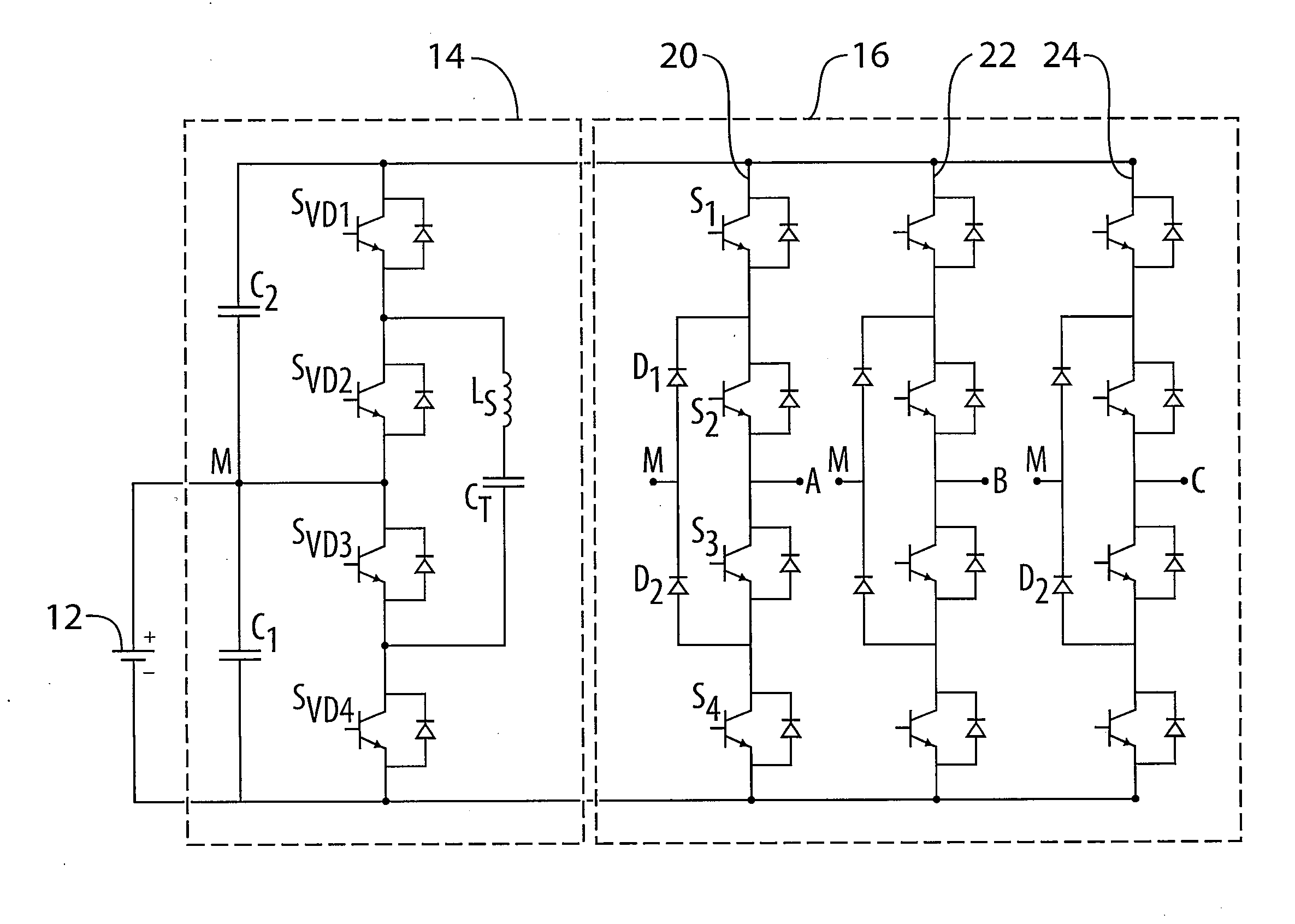
[0018]FIG. 2 shows the topology of a circuit 10 according to a preferred embodiment invention which includes a voltage doubler 14 connected between a battery 12 and an inverter 16. As described in greater detail below, the voltage doubler 14 selectively is capable of supplying the inverter 16 with a voltage approximately twice the voltage Vbat of the battery 12. And unlike the prior art NPC PWM inverter, inverter 16 is selectively controlled in one of two modes either as a conventional PWM inverter or as a multi-level clamped inverter depending on power requirements as discussed in greater detail below.

[0019]More particularly, the voltage doubler 14 includes a first capacitor C1 connected in parallel with the battery 12. A second capacitor C2 is connected in series with C1 with the positive battery terminal connected to node M between C1 and C2. An energy transfer path includes switches SVD1, SVD2 disposed opposite C2, switches SVD3, SVD4 disposed opposite C1 as shown. The junction ...


PUM


Abstract

A boost inverter includes a first capacitor for connection in parallel with a dc supply voltage; a second capacitor connected in series with the first capacitor; an energy transfer path including a transfer capacitor and switches connected to the transfer capacitor for cyclically transferring energy from the first capacitor to the transfer capacitor and then from the transfer capacitor to the second capacitor; a multilevel inverter circuit connected in parallel with the series combination of the first and second capacitors, the inverter having at least one phase output for connection to an electric motor; and a PWM controller that activates the energy transfer path when a desired peak-to-peak output voltage exceeds the dc supply voltage and deactivates the energy transfer means when the desired peak-to-peak output voltage is less than the dc supply voltage.

Description

[0001]This application claims the benefits of U.S. Provisional Application No. 61 / 285,612, filed Dec. 10, 2010.FIELD OF THE INVENTION[0002]The invention relates to the art of switch-mode dc-to-ac inverters, and more particularly to a PWM inverter capable of supplying an output voltage higher than a dc supply voltage.BACKGROUND OF THE INVENTION[0003]Electric and / or hybrid internal combustion engine (ICE) and electric vehicles can utilize relatively large motors. For example, an electric-only vehicle may be powered by a 100 kilowatt electric motor, driven off of a 300 V battery pack.[0004]At such power ratings, it is desirable to minimize the magnitude of current flowing through the inverter and electric motor to reduce I2R power losses and reduce the size of wires and their connectors. Lower current flows can also enable the electric motor to be made smaller and have less heat loss. However, this objective must be balanced against the voltage that the battery provides and the breakdo...

Claims


Application Information

Patent Timeline
IPC IPC(8): H02M7/44
CPCH02M3/158H02M7/487H02M2001/007H02M1/007
Inventor JOSEPH, ALAN
Owner MAGNA E CAR SYST OF AMERICA
Why Eureka
Try Eureka