

Transmitting apparatus and method, and receiving apparatus and method
Active Publication Date: 2011-06-16
SONY CORP
View PDF4 Cites 15 Cited by
- Summary
- Abstract
- Description
- Claims
- Application Information
AI Technical Summary
Benefits of technology
The network-responsive buffer period calculating means may set, as the network-responsive buffer period, a largest one of a network-jitter-responsive buffer period, a rate-ratio-responsive buffer period, and a retransmission-responsive buffer period, the network-jitter-responsive buffer period being a minimum buffer period necessary to prevent the synchronous reproduction from failing due to an increased delay caused by the network jitter of the network, the rate-ratio-responsive buffer period being a minimum buffer period necessary to prevent the synchronous reproduction from failing due to a ratio of the transmission rate to an encoding rate at which the encoding means encodes the image data, the retransmission-responsive buffer period being a minimum buffer period necessary to prevent the synchronous reproduction from failing due to a delay caused by a retransmission process.
According to the embodiments of the present invention, data can be transmitted. In particular, low-delay data transmission with reduced unnecessary delay periods can be performed in a more stable manner irrespective of the network status.
Problems solved by technology
However, if the network environment is unstable and per-packet transmission delay variations occur due to the change in transmission rate, network jitter, packet loss, or the like, buffering and decoding reproduction in accordance with a buffering period written in the transmission format at the time of encoding may cause buffer failure due to the lack of necessary data at the reproduction time.
Method used
View moreImage
Smart ImageViewing Examples

Examples
first embodiment (
1. First Embodiment (first transmitting / receiving system)
second embodiment (
2. Second Embodiment (second transmitting / receiving system)
third embodiment (
3. Third Embodiment (third transmitting / receiving system)
Login to View More PUM
 Abstract
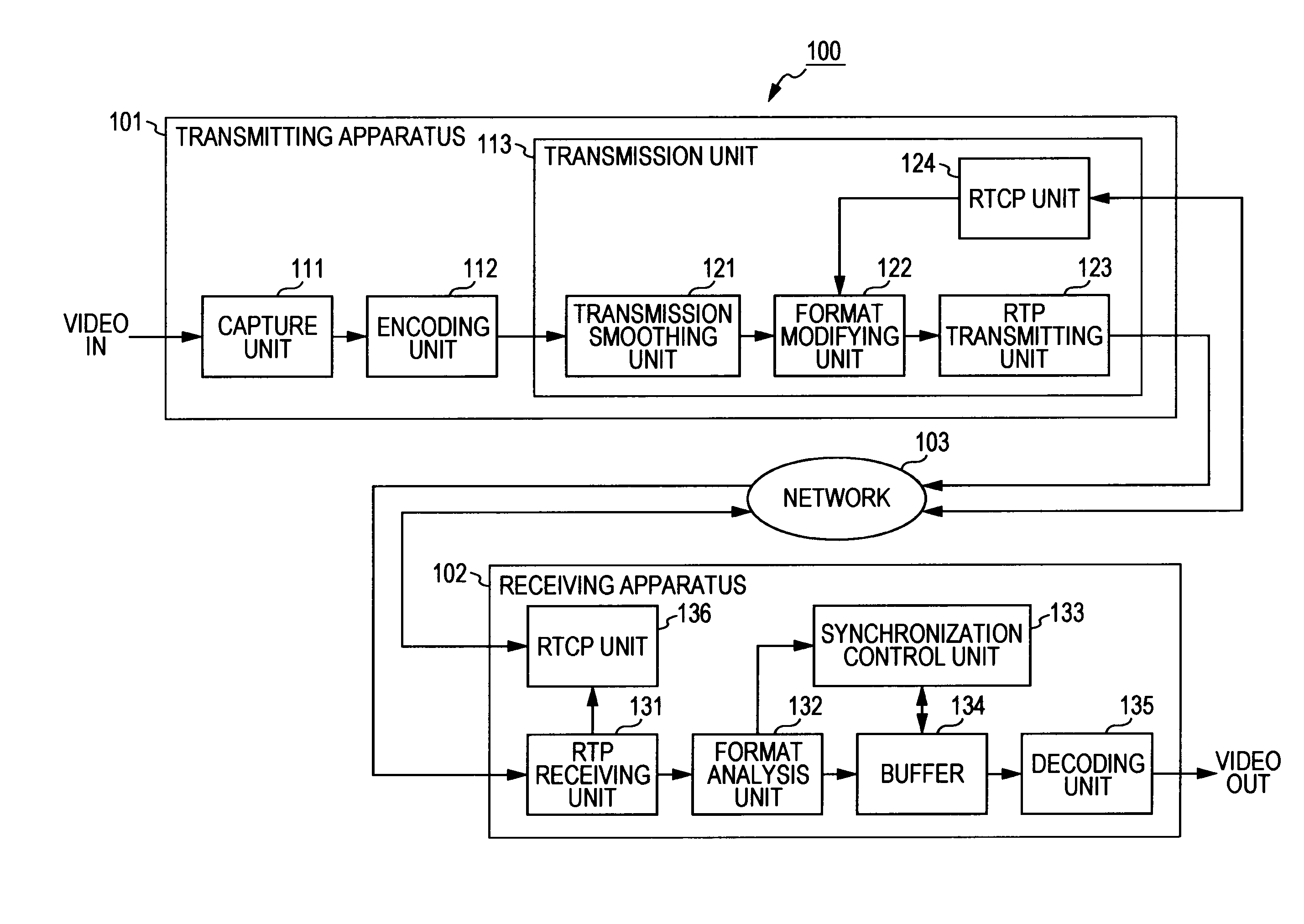
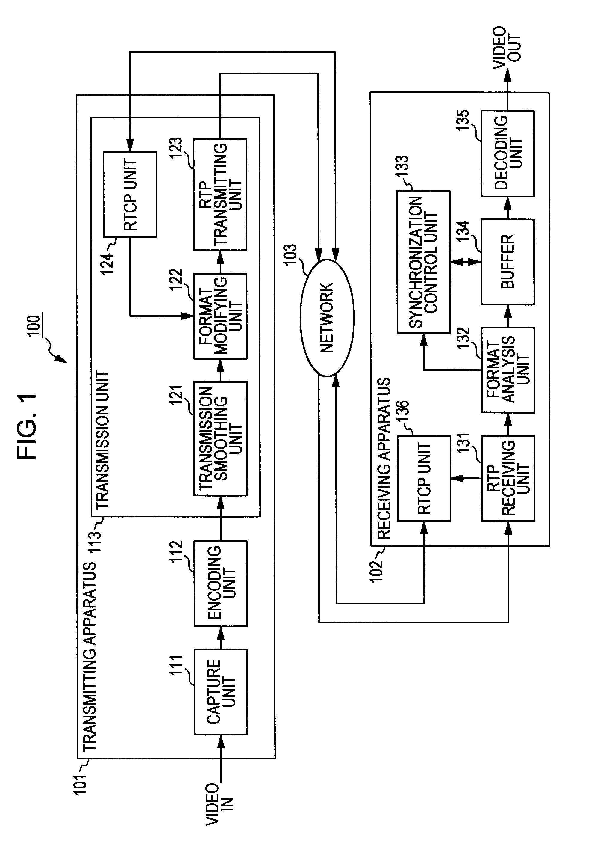
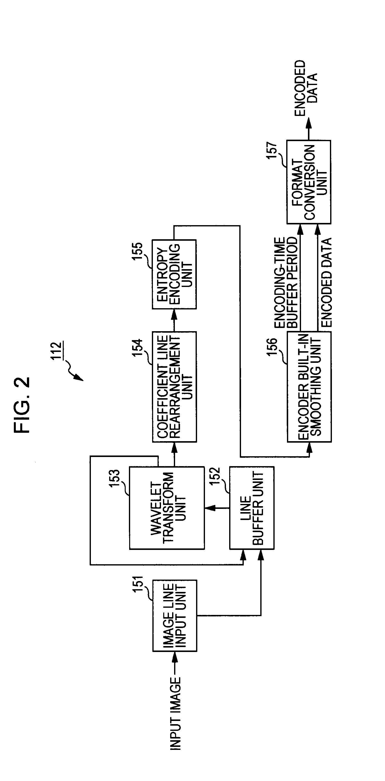
Image data is encoded to generate encoded data. An encoding-time buffer period that is a minimum buffer period necessary to prevent synchronous reproduction in which the encoded data is decoded and reproduced in synchronization with a timestamp added to the encoded data from failing due to a delay caused by encoding of the image data is added to the encoded data as encoding header information. A transmission-time buffer period that is a minimum buffer period necessary to prevent the synchronous reproduction from failing due to a delay caused by encoding of the image data and transmission of the encoded data is added to the encoded data as transmission header information different from the encoding header information. The encoded data having the encoding-time buffer period and the transmission-time buffer period added thereto is transmitted to another apparatus that performs the synchronous reproduction via a network.
Description
BACKGROUND OF THE INVENTION1. Field of the InventionThe present invention relates to a transmitting apparatus and method, and a receiving apparatus and method. More specifically, the present invention relates to a transmitting apparatus and method, and a receiving apparatus and method that provide low-delay data transmission with reduced unnecessary delay periods in a more stable manner irrespective of the network status.2. Description of the Related ArtIn recent years, the demand for low-delay transmission of multimedia data via the Internet or any other transmission path has increased. For example, applications for allowing an operator in a remote place to operate surgical instrument in the operating room while viewing the operating room scenes of a moving image transmitted from the operating room, called telesurgery applications, are available. In such applications, it is desirable that a moving image be transmitted with a delay less than a several frame interval in order to incr...
Claims
Login to View More Application Information
Patent Timeline
 IPC IPC(8): G06K9/36H04L12/70H04N21/44H04N7/173H04N21/6332
CPCH04L65/80H04L65/4069H04L65/61
InventorKURE, YOSHINOBU
OwnerSONY CORP