
Converting aircraft enhanced vision system video to simulated real time video

Active Publication Date: 2011-06-16
HONEYWELL INT INC
View PDF13 Cites 13 Cited by
  • Summary
  • Abstract
  • Description
  • Claims
  • Application Information

AI Technical Summary

Benefits of technology

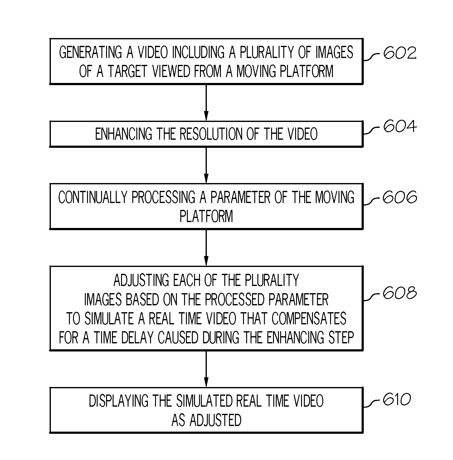
[0007]A method for overcoming image latency issues of a enhanced vision system includes generating a video comprising a plurality of images of a target viewed from a moving platform, enhancing the resolution of the video, processing a parameter of the moving platform related to the relative position of the platform to the target, adjusting each of the plurality of images based on the processed parameter to simulate a real time video, and displaying the simulated real time video.

Problems solved by technology

The approach to landing and touch down on the runway of an aircraft is probably the most challenging task a pilot undertakes during normal operation.
An approach outside of this envelope can result in an undesirable positioning of the aircraft with respect to the runway, resulting in possibly discontinuance of the landing attempt.
In some instances visibility may be poor during approach and landing operations.
However, Enhanced Vision Systems (EVS) images, for example, from an InfraRed camera, typically produce video output of lower resolution with substantial image noise, often due to inherent limitation of both device, physics, and external conditions, thereby impeding a pilot's recognition and understanding of the object or objects being displayed leading to significant target recognition and high training requirements for flight crews.
Although such enhancing approaches can produce significantly improved images with increased resolution and feature definition, they typically introduce significant delays detrimental to aircraft control, particularly when such EVS images are presented onto a heads-up-display or a heads-down primary flight display for approach and landing operations.

Method used


Image

  • Converting aircraft enhanced vision system video to simulated real time video
  • Converting aircraft enhanced vision system video to simulated real time video
  • Converting aircraft enhanced vision system video to simulated real time video

Examples


Embodiment Construction

[0017]The following detailed description of the invention is merely exemplary in nature and is not intended to limit the invention or the application and uses of the invention. Furthermore, there is no intention to be bound by any theory presented in the preceding technical field, background, brief summary, or the following detailed description.

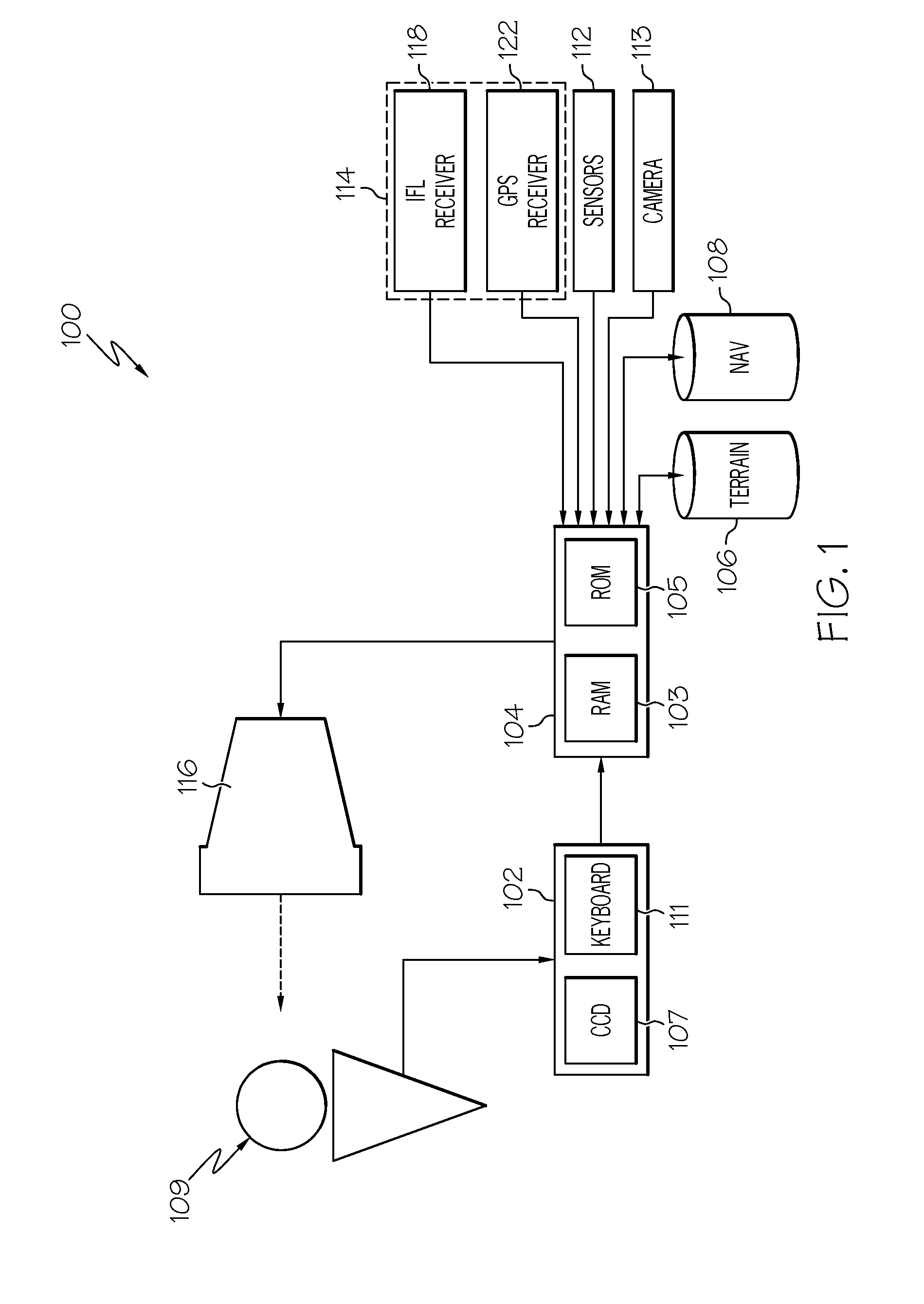
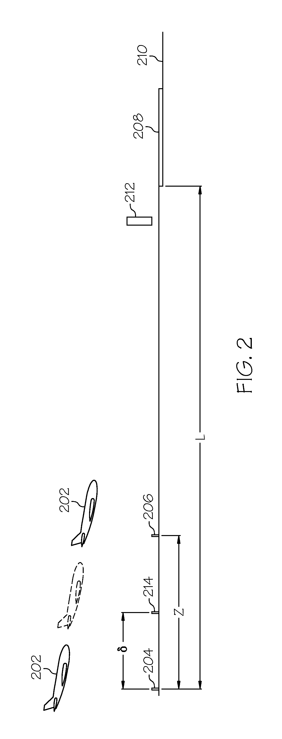
[0018]An approach is described herein for overcoming image latency issues of an Enhanced Vision System (EVS) that uses, for example, on-board GPS, inertial, and attitude sensors to quicken the enhanced video image so it is displayed with the correct visual dimensions for the current position of the aircraft for approach and landing operations. For example, when an aircraft approaches a runway, the actual images on the ground increase in size. By enlarging the displayed image, when the aircraft is approaching the target, to match a time interval between fixed time intervals of the otherwise displayed enhanced images, the flight crew does not e...


PUM


Abstract

A method for overcoming image latency issues of a synthetic vision system include generating (602, 704) a video comprising a plurality of images (300, 400, 500) of a target (208, 212) viewed from a moving platform (202), enhancing (604, 704) the resolution of the video, processing (606, 706) a parameter of the moving platform (202) related to the relative position of the platform to the target (208, 212), adjusting each of the plurality of images based on the processed parameter to simulate a real time video, and displaying (610, 710) the simulated real time video.

Description

FIELD OF THE INVENTION[0001]The present invention generally relates to the display of target images to an aircrew and more particularly to converting and displaying a target image, such as a simulated landing environment, to a real time image.BACKGROUND OF THE INVENTION[0002]Pilots typically rely on both ground references and instruments when navigating from one point to another. Aircraft flying at 35,000 feet generally rely more on instruments while aircraft flying close to the ground typically rely more on ground references. During approach and landing, they may rely more on ground references if the weather permits.[0003]The approach to landing and touch down on the runway of an aircraft is probably the most challenging task a pilot undertakes during normal operation. To perform the landing properly, the aircraft approaches the runway within an envelope of attitude, course, speed, and rate of descent limits. The course limits include, for example, both lateral limits and glide slo...

Claims


Application Information

Patent Timeline
IPC IPC(8): G06K9/00
CPCG01C23/00G02B27/01G09B9/302G02B2027/014G02B2027/0138
Inventor HE, GANG
Owner HONEYWELL INT INC
Learn More