Piercing tip for scrap shear

a scrap shear and piercing technology, applied in the field of scrap shear piercing tips, can solve the problems of physical destruction of the shear blades, wear and even destruction of the cutting and bearing edges of scrap shears, and the maintenance of the machinery employed in metal reduction and recycling, so as to reduce scrap materials and maintain the engagement of the piercing tip

Inactive Publication Date: 2011-06-23
PURSER BRIAN
View PDF0 Cites 12 Cited by
  • Summary
  • Abstract
  • Description
  • Claims
  • Application Information

AI Technical Summary

Benefits of technology

[0016]According to yet another embodiment of the invention, a shearing apparatus for reducing scrap material includes a first member having a first jaw on an end thereof, a second member pivotally mounted to the first member for movement about a pivot axis, and a second jaw carried by the second member opposing the first jaw. The second jaw is movable about the pivot axis relative to the first jaw between a relatively open position for receiving scrap material between the first jaw and the second jaw and a cl

Problems solved by technology

As with any bladed tool, the cutting and bearing edges of scrap shears are subject to wear and even destruction.
The forces involved in piercing and shearing large metal waste structures are considerable, and so maintaining the machinery employed in metal reduction and recy

Method used


Image

  • Piercing tip for scrap shear
  • Piercing tip for scrap shear
  • Piercing tip for scrap shear

Examples


Embodiment Construction

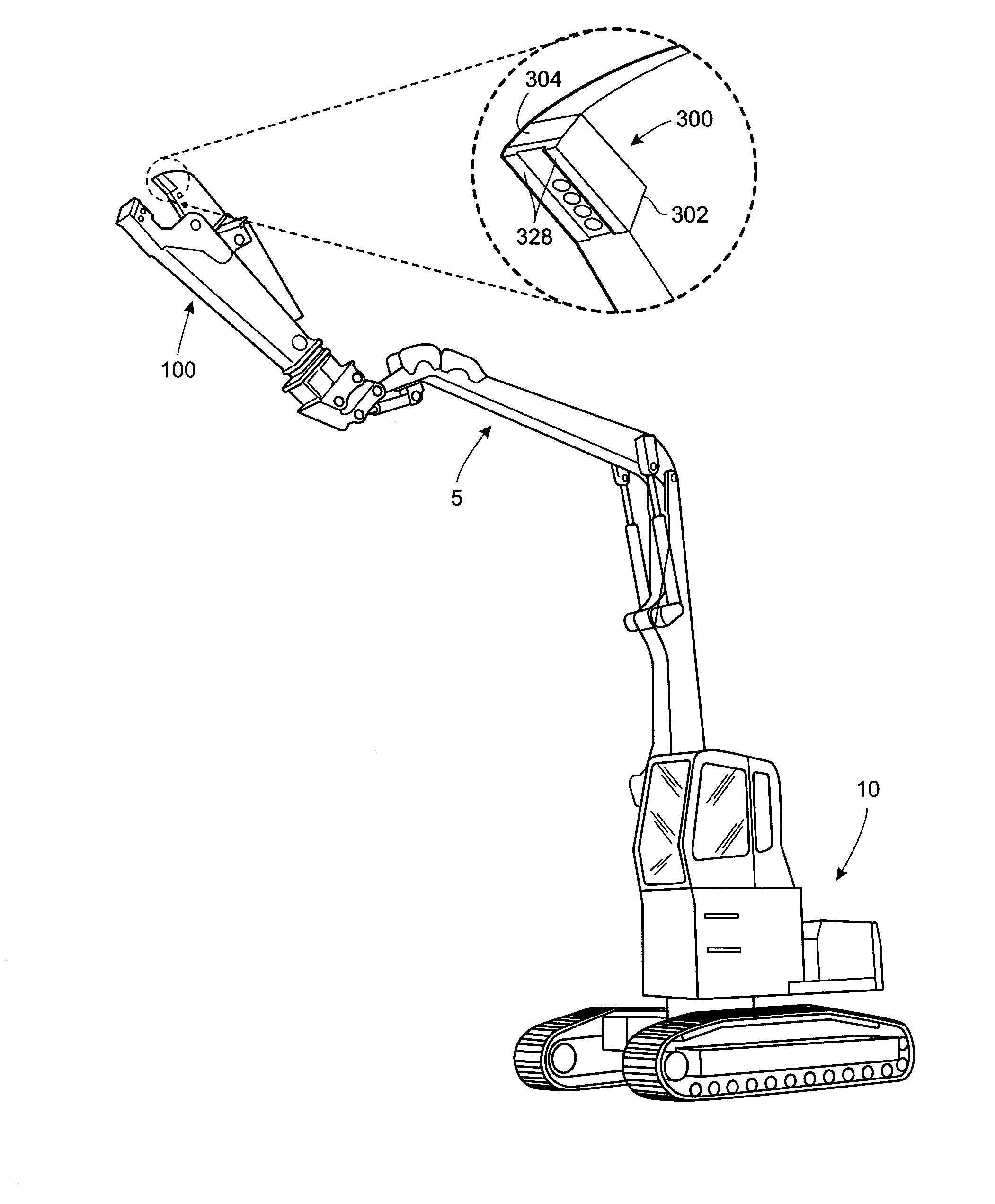
[0023]Referring to the drawings wherein identical reference numerals denote the same elements throughout the various views, FIG. 1 illustrates a shearing apparatus 100 according to one embodiment of the present invention. The shearing apparatus 100 is carried by the movable mechanical arm 5 of an industrial vehicle 10 and is positioned by the operator of the vehicle 10 to shear materials such as scrap metal.

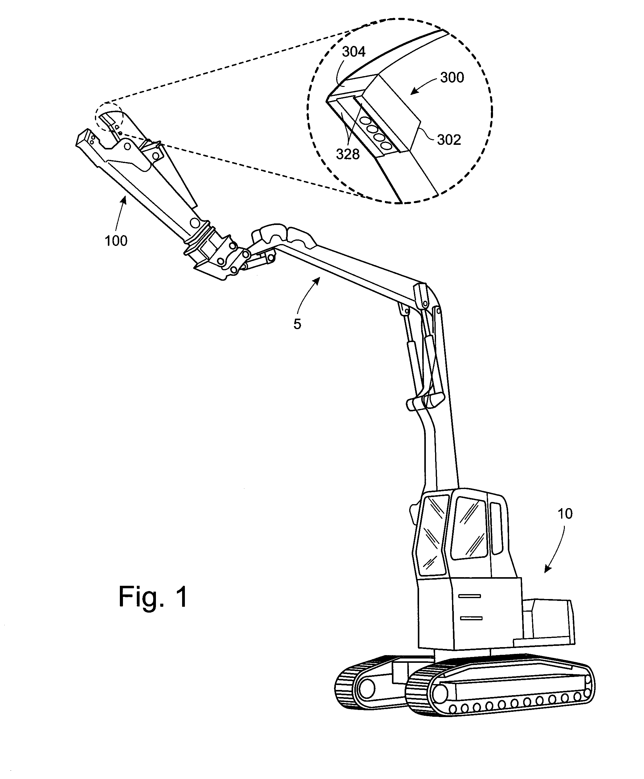
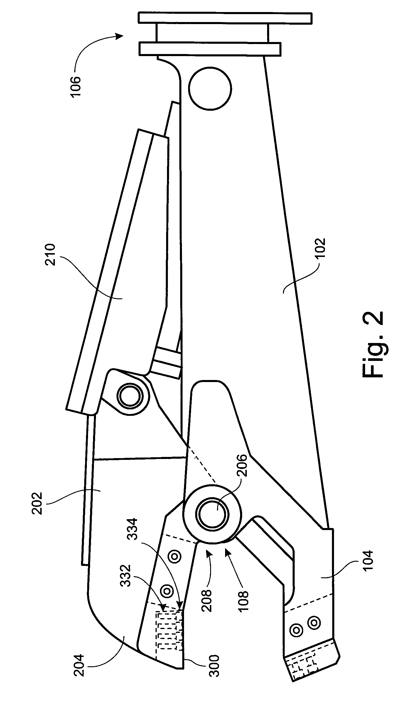
[0024]The shearing apparatus 100, as shown separately in FIG. 2, includes a first member 102 having a first jaw 104 and a mounting means 106 at the opposite end of the first member 102. The mounting means 106 attaches to the mechanical arm 5 of the industrial vehicle 10, such as the illustrated backhoe as shown in FIG. 1.

[0025]As is also shown in FIG. 2, the shearing apparatus 100 includes a second member 202 having a second jaw 204 that opposes the first jaw 104. The first and second members 102 and 202 have respective pivot brackets 108 and 208 that engage a pin 206 about which...


PUM

PropertyMeasurementUnit
Widthaaaaaaaaaa

Abstract

A piercing tip for a jaw of a shearing apparatus includes a main body having an open linear slot formed therein, and a complementary linear channel formed in the main body parallel to and open to the slot to capture within the channel an enlarged elongate head of a jaw of a shearing apparatus. A jaw for a shearing apparatus includes a raised rail, an enlarged elongate head positioned along the raised rail, and a piercing tip for piercing the scrap material upon movement of the jaw to the closed position. The piercing tip has a slot formed therein for receiving the raised rail and a widened channel formed in the slot for receiving the enlarged elongate head to maintain the engagement of the piercing tip with the second jaw.

Description

TECHNICAL FIELD OF THE INVENTION[0001]This invention relates generally to an apparatus for reducing scrap materials, and more particularly to a piercing tip for a scrap shear.BACKGROUND OF THE INVENTION[0002]Shears of various designs are attached to the mechanical arms of backhoes, earth-moving vehicles, and other industrial vehicles and are employed to sever, reduce, and move scrap materials for recycling or disposal. As with any bladed tool, the cutting and bearing edges of scrap shears are subject to wear and even destruction. The forces involved in piercing and shearing large metal waste structures are considerable, and so maintaining the machinery employed in metal reduction and recycling represents considerable costs. Machine operators are typically operating within a time schedule, and are often dealing with irregular piles of scrap and a variety of scrap configurations including rails, sheets, beams, and a wide variety of other scrap materials. Thus, the action at the cuttin...

Claims


Application Information

Patent Timeline
IPC IPC(8): B26D1/38B26D7/26
CPCB23D31/008B23D35/002Y10T83/9457Y10T83/9447Y10T83/7513
Inventor PURSER, BRIAN
Owner PURSER BRIAN
Why Eureka
Try Eureka