Fall protection safety device with a braking mechanism

a safety device and braking mechanism technology, applied in the direction of safety belts, hoisting equipment, building scaffolds, etc., can solve the problems of wheel contamination, wheel may not operate properly,

Active Publication Date: 2011-06-23
D B IND
View PDF13 Cites 90 Cited by
  • Summary
  • Abstract
  • Description
  • Claims
  • Application Information

AI Technical Summary

Benefits of technology

In one embodiment, a fall protection safety device including a braking mechanism comprises a housing, a pawl, and a magnet. The housing is configured and arranged to move along a support structure being from the group consisting of a rail, a track, and a cable and being made of a non-ferromagnetic and electrically conductive material. The pawl is pivotally connected to the housing and is configured and arranged to move from a d

Problems solved by technology

If the shuttle becomes contaminated with dirt, oil, grease, water, ice, or other types of debris or contaminants, the shuttle may not operate proper

Method used


Image

  • Fall protection safety device with a braking mechanism
  • Fall protection safety device with a braking mechanism
  • Fall protection safety device with a braking mechanism

Examples


Embodiment Construction

In the following detailed description, reference is made to the accompanying drawings, which form a part hereof, and in which is shown by way of illustration embodiments in which the inventions may be practiced. These embodiments are described in sufficient detail to enable those skilled in the art to practice the invention, and it is to be understood that other embodiments may be utilized and mechanical changes may be made without departing from the spirit and scope of the present invention. The following detailed description is, therefore, not to be taken in a limiting sense, and the scope of the present invention is defined only by the claims and equivalents thereof.

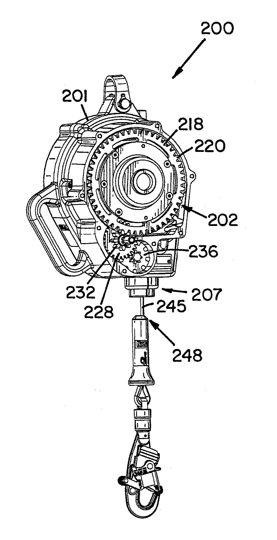
The present invention generally relates to a braking mechanism for use with a fall protection safety device. The braking mechanism could act as a brake, a lock, and / or a trigger mechanism suitable for the type of fall protection safety device.

One type of fall protection safety device with which the present invention c...


PUM


Abstract

A fall protection safety device including a braking mechanism comprises a first component, a second component configured and arranged to move relative to the first component, and at least one magnet operatively connected to one of the components and another of the components being at least partially made of a non-ferromagnetic and electrically conductive material. The at least one magnet and the non-ferromagnetic and electrically conductive material creating an electromagnetic field force when the second component moves at a rate greater than a predetermined rate relative to the first component.

Description

FIELD OF THE INVENTIONThe present invention relates to a fall protection safety device including a braking mechanism.BACKGROUNDFall protection safety devices are well known in the art of fall protection safety equipment for use by workers performing tasks during which there is a risk a fall may occur.One type of safety device commonly used is a rail along the length of which a shuttle moves. The rail is typically connected to a support structure within the vicinity the worker is performing the task, and the shuttle is typically connected to a safety harness worn by the worker. An energy absorber may also be used with this type of safety device to reduce the amount of force transferred to the worker. Should a fall occur, the shuttle locks onto the rail thereby preventing the worker from falling any further. If the shuttle becomes contaminated with dirt, oil, grease, water, ice, or other types of debris or contaminants, the shuttle may not operate properly. One type of commonly used s...

Claims


Application Information

Patent Timeline
IPC IPC(8): F16D65/21B65H59/16A62B1/08A62B1/10F16D65/18
CPCA62B1/14H02K49/043A62B35/0062A62B35/0081
Inventor BLOMBERG, JOHN P.
Owner D B IND
Why Eureka
Try Eureka