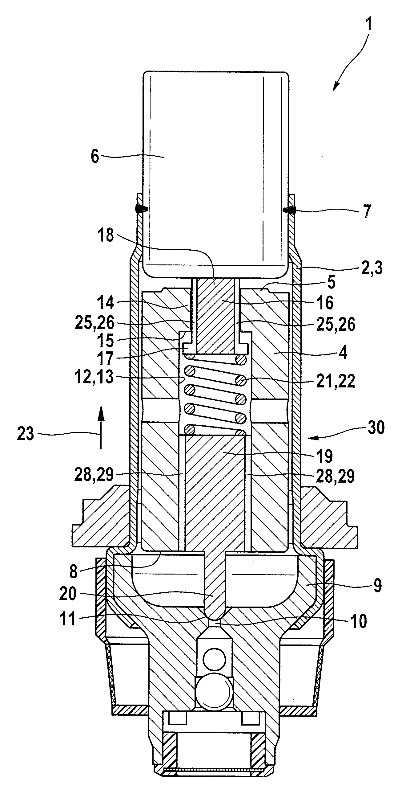
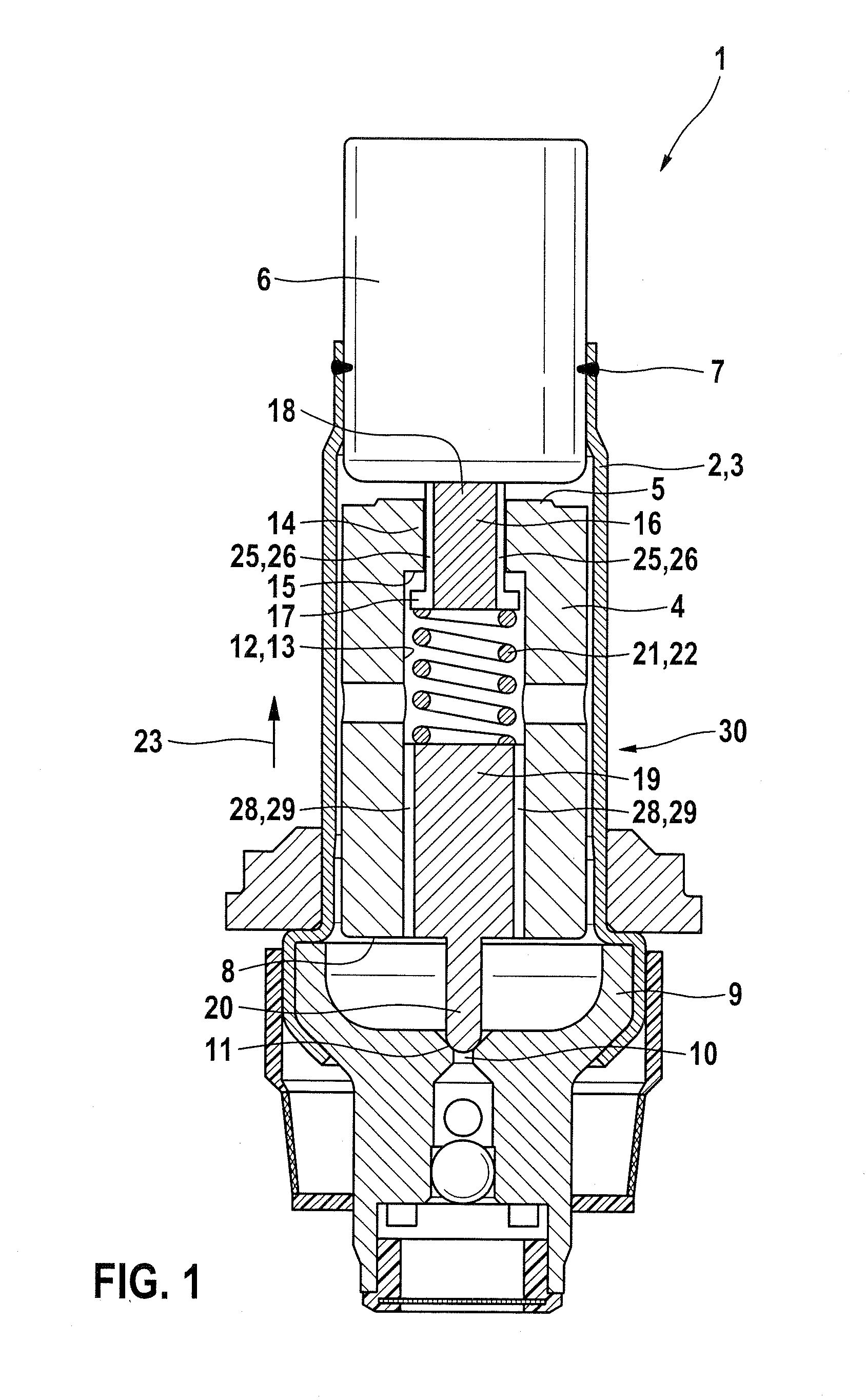
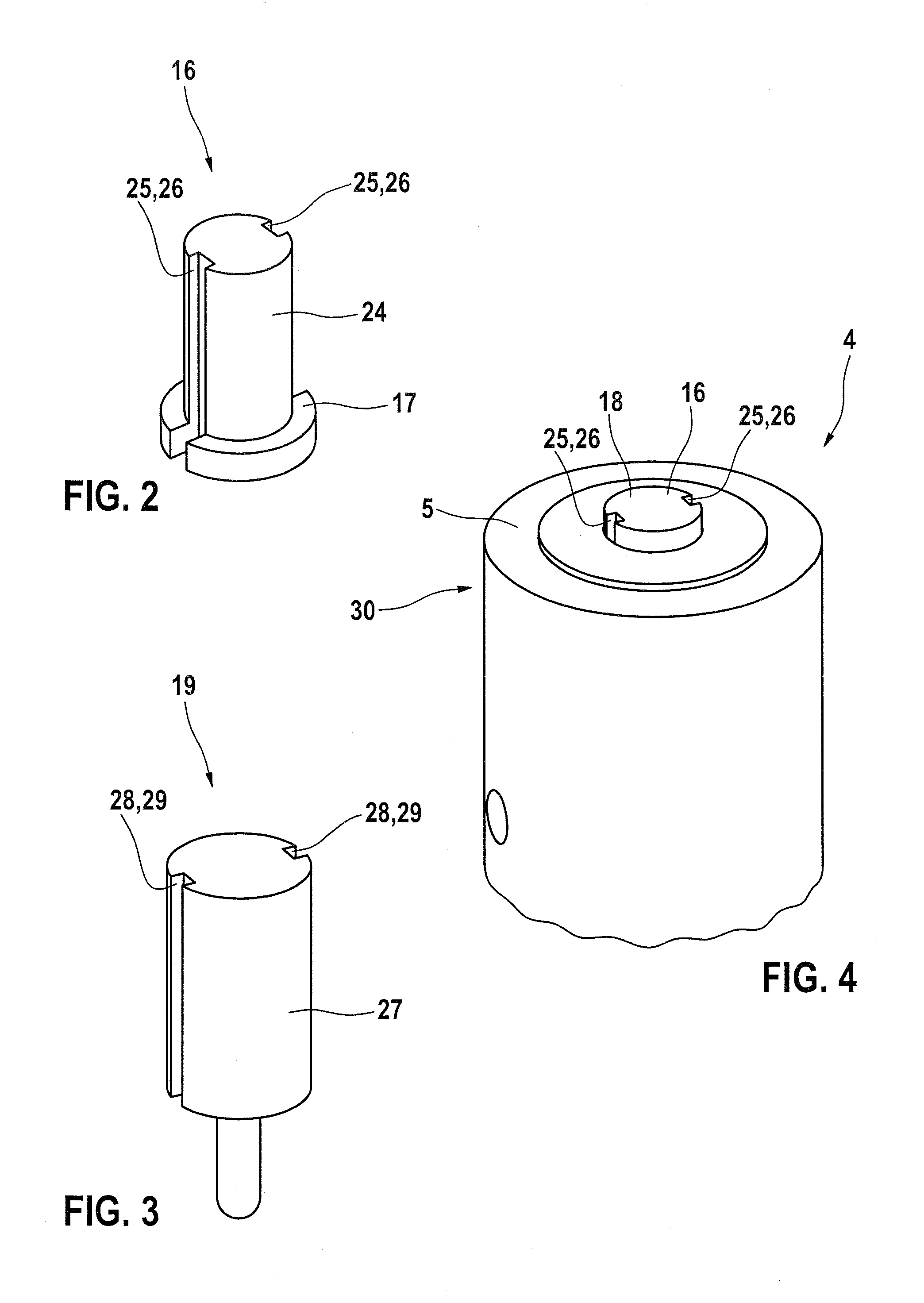
[0008]The solenoid valve of the invention has the advantage that first, existing tolerances can be taken into account and / or compensated for very much better, and second, that the maximum operative magnetic force is increased. The solenoid valve of the invention is distinguished in that the compression spring is held in prestressed fashion in an axial passage of the armature, between a bolt, having the valve sealing body and held in a selectable position in the axial passage in force- and / or form-locking fashion, and a thrust piece, disposed such that it can be pushed out of the axial passage up to a stop and subjects the pole core to the prestressing force. Thus the armature has an axial passage, which extends axially in conduitlike fashion through the entire armature. Preferably, the axial passage is embodied centrally, or centrally / coaxially. In the simplest case, the axial passage is embodied as a through bore. The compression spring rests in this axial passage and is kept prestressed between the bolt and the thrust piece. The bolt has the valve sealing body; it is understood that the valve sealing body is disposed on the bolt, on the side of the bolt facing away from the armature, so that this sealing body can cooperate with the sealing seat of the solenoid valve. The bolt is kept in a selectable position in the axial passage in force- and / or form-locking fashion. This means that the bolt can be held or secured in various axial positions in the axial passage. Its position in the axial passage is defined by a force- and / or form-locking connection. As a result, it is possible upon assembly to insert the bolt variously far into the axial passage and keep it there. The thrust piece is disposed such that it can be pushed up to a stop out of the axial passage. The movement travel of the thrust piece in the axial passage is accordingly limited by the stop, in such a way that the thrust piece cannot be pushed all the way out of the axial passage. However, until it reaches the stop, the thrust piece is entirely freely (axially) shiftable. In the assembled state, the thrust piece subjects the pole core to the prestressing force of the compression spring. This means that in the assembled state, the thrust piece is kept spaced apart from the axial stop, since then the movement travel of the thrust piece is limited by the pole core. Upon assembly of the solenoid valve, it is now possible to adjust the prestressing force of the compression spring precisely. By displacement of the bolt into the axial passage, the compression spring is tensed against the thrust piece, which upon assembly is in a practical way not yet acted upon by the pole core but instead rests on the stop of the armature. As a result, the spring chamber is clearly defined, and the prestressing force can be calculated for instance as a function of the displacement travel of the bolt. Preferably, however, the bolt is inserted iteratively or piece by piece farther and farther into the axial passage, until the desired prestressing force is reached, and the prestressing force is detected after every incremental insertion of the bolt, in particular by subjecting the thrust piece to a defined contrary force in the direction of the compression spring. Advantageously, the contrary force is selected such that it corresponds to the desired prestressing force. If the thrust piece can then, because of the contrary force, no longer be shifted axially into the armature, then the desired prestressing force has been reached. Next, the armature is constructed together with the bolt, compression spring and thrust piece, as a preassembled unit. Thus in a simple way, the solenoid valve makes it possible to adjust the prestressing force of the spring precisely and thus to compensate for given part tolerances.
[0009]Preferably, the bolt is press-fitted into the axial passage. Thus the bolt and the axial passage form a press fit, which keeps the bolt in force-locking fashion in the axial passage. For inserting the bolt, in order to adjust the prestressing force of the compression spring, all that has to be done is for the clamping force of the press fit to be overcome. This affords especially simple locking of the bolt in a desired position in the axial passage. Alternatively, a self-locking thread would also be conceivable, by means of which the bolt can be screwed into the axial passage until the desired prestressing force is reached.
[0010]Advantageously, the thrust piece is embodied in T-shaped fashion; with its at least essentially cylindrical base body which is a longitudinal beam, it protrudes out of the axial passage, so that it can subject the pole core to the prestressing force. A radial protrusion which is a transverse beam extending over the circumference of the base body cooperates with a protrusion that protrudes into the axial passage and forms the stop. The T-shaped embodiment of the thrust piece is understood in this connection to refer to the contour of the thrust piece in longitudinal section.
[0011]Advantageously, the axial passage is embodied in tapered form on the end associated with the pole core. This results in the embodiment of the protrusion that acts as a stop. Preferably, the taper is embodied as a step, so that the protrusion forms an axial stop face.
[0012]Advantageously, the compression spring is embodied as a helical spring. Because of its long-term load-bearing capacity, this permits long-term reliable operation of the solenoid valve.
[0013]It is moreover provided that the bolt and / or the thrust piece each have at least one longitudinal slot on their outer jacket face. The longitudinal slot extends from one end to the other end of the bolt or thrust piece, as applicable, so that a fluid communication or a fluid conduit along the bolt and / or the thrust piece is offered, through which the fluid, such as brake fluid, can flow during a reciprocation event. As a result, the otherwise usual longitudinal slots provided on the outer jacket face of the armature can be omitted, so that the armature is advantageously embodied as free of longitudinal slots. As a result, the cross-sectional area relevant to the magnet actuator system is increased. Thus the maximum possible magnet force with which the armature can be actuated is increased.

