Systems and methods for operating piezoelectric switches

Active Publication Date: 2011-06-23
THE TRUSTEES OF THE UNIV OF PENNSYLVANIA
View PDF1 Cites 5 Cited by
  • Summary
  • Abstract
  • Description
  • Claims
  • Application Information

AI Technical Summary

Benefits of technology

[0011]According to still another aspect of the present invention, a logic element is disclosed. The logic element includes an array of piezoelectric switches and one or more bias voltage sources. The array of piezoelectric switches are arranged on a substrate. Each switch comprises a first actuator including a first body electrode, a first gate electrode, and a first contact region, and

Problems solved by technology

Semiconductor switches may suffer from

Method used


Image

  • Systems and methods for operating piezoelectric switches
  • Systems and methods for operating piezoelectric switches
  • Systems and methods for operating piezoelectric switches

Examples


Embodiment Construction

[0038]FIGS. 12-15 illustrate aspects of the present invention relating to exemplary piezoelectric switching systems and exemplary methods of operating piezoelectric switches.

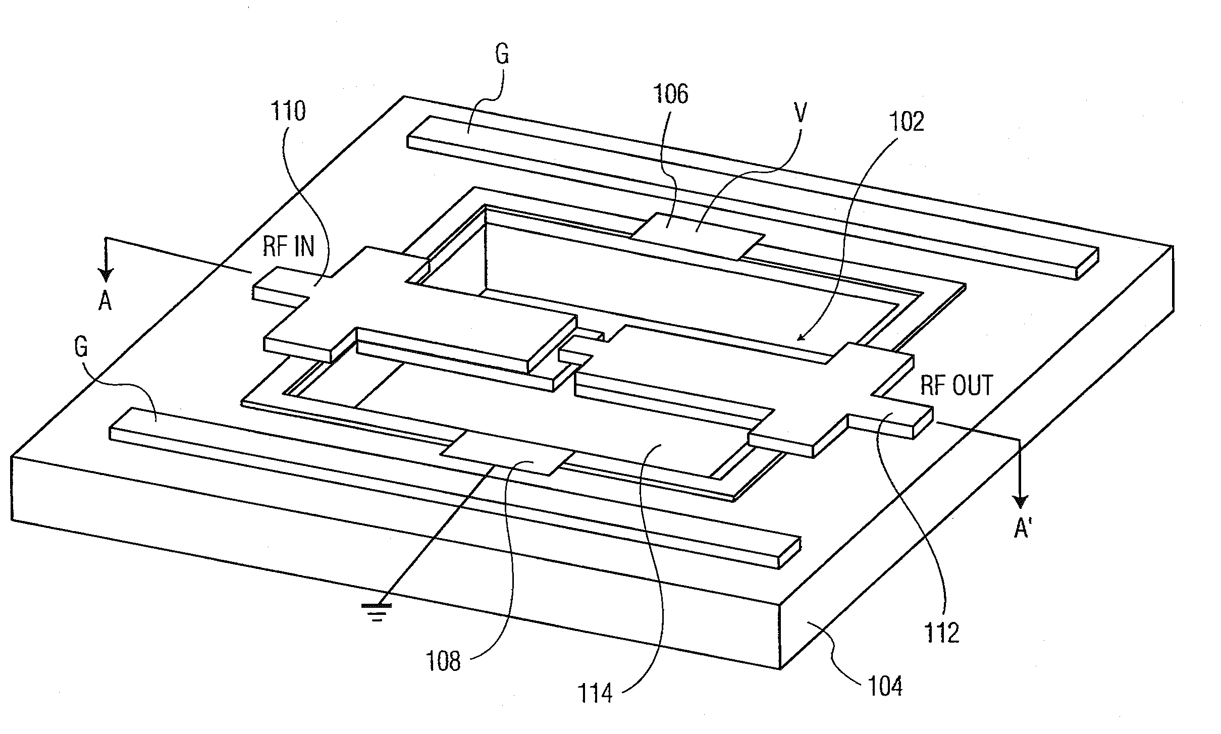
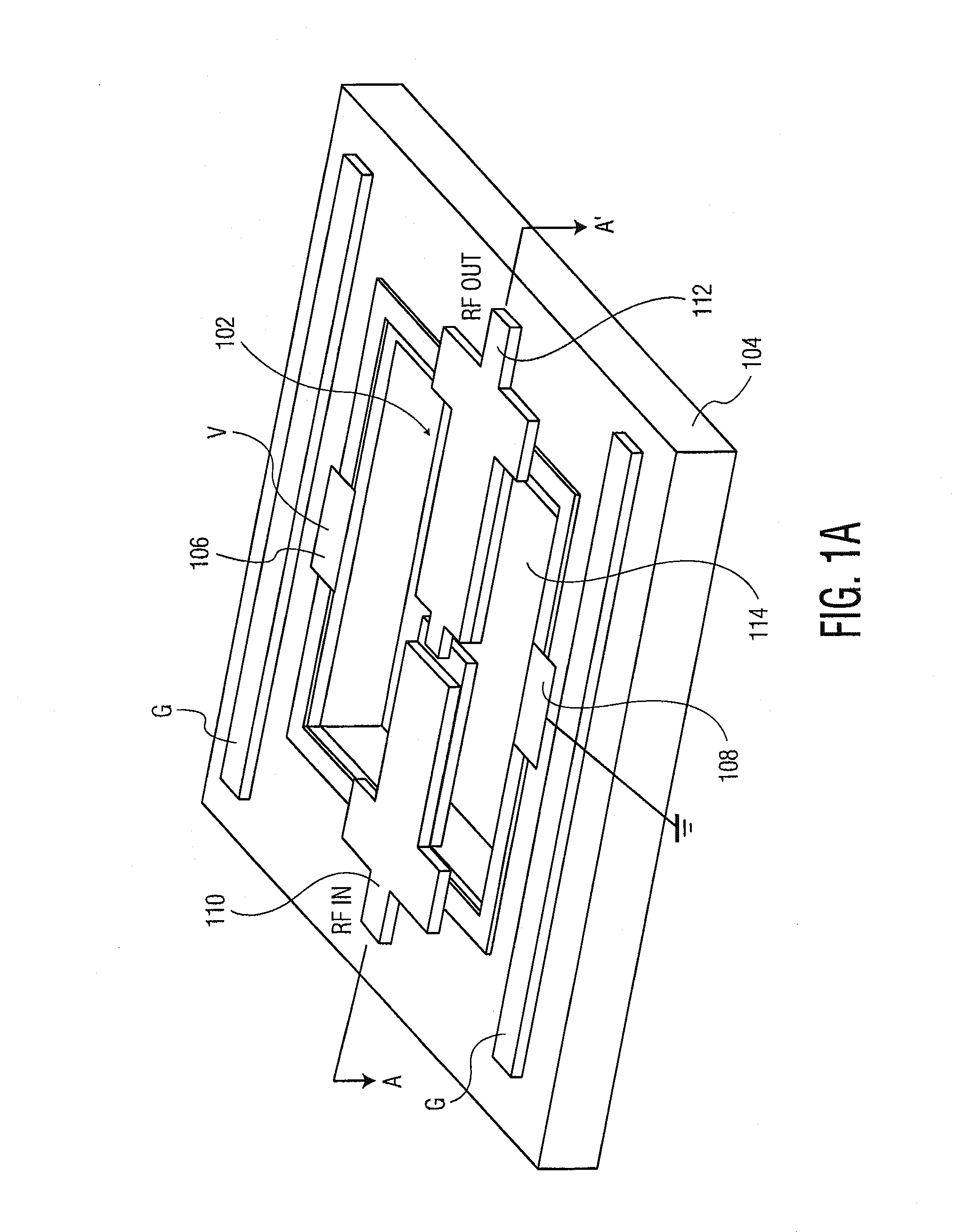
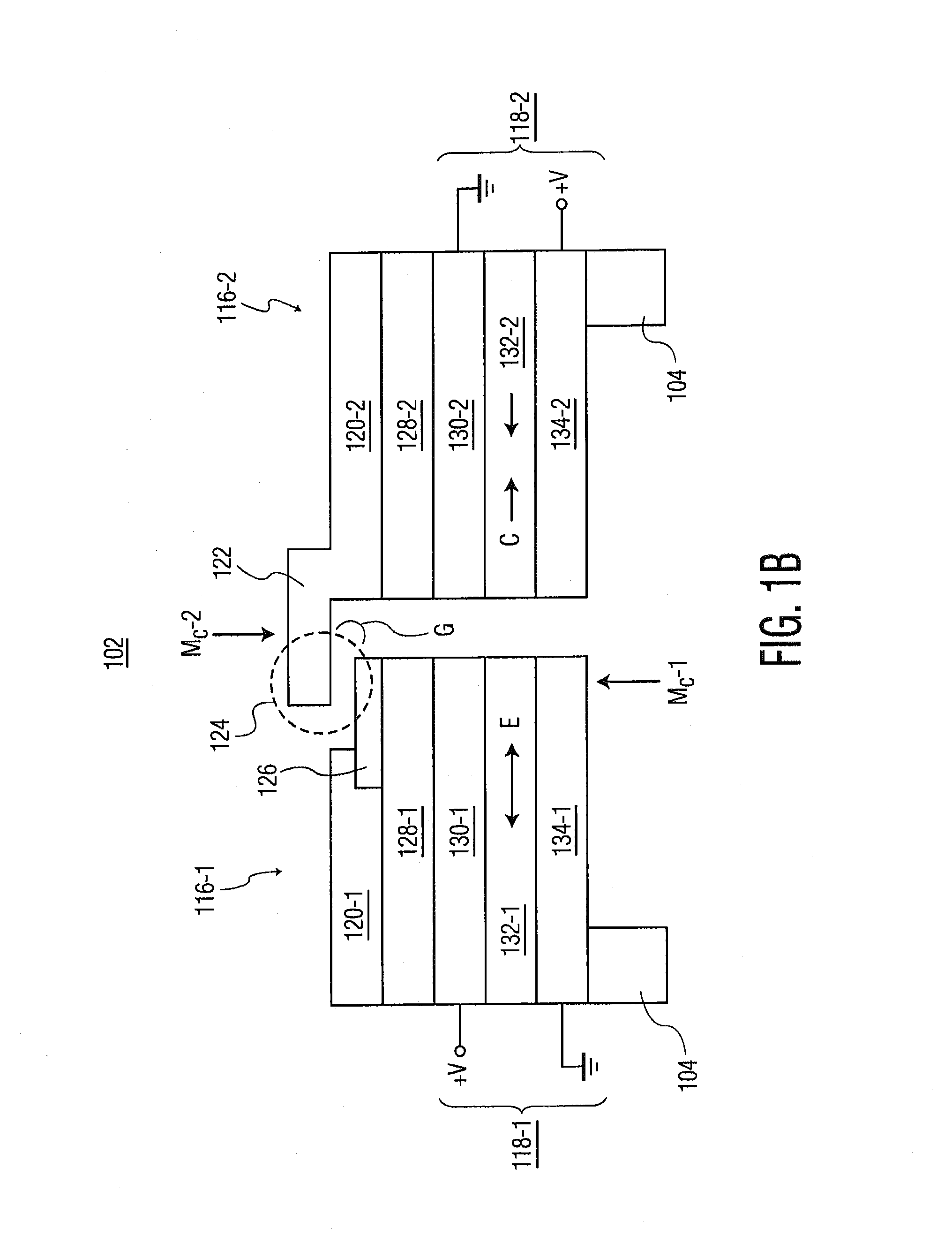
[0039]FIGS. 12 and 13 depict an exemplary piezoelectric switching system 5 in accordance with one aspect of the present invention. As a general overview, piezoelectric switching system 5 includes a first actuator 10, a second actuator 30, and a bias voltage source 50. First and second actuators 10 and 30 may desirably be cantilever beam actuators. First and second actuators 10 and 30 may be coupled to a substrate (not shown) such that a portion of actuators 10 and 30 is suspended from the substrate, allowing actuators 10 and 30 to bend. The illustrated embodiment will now be described below in further detail.

[0040]First actuator 10 includes body electrode 12, a pair of gate electrodes 14 and 15, layers of piezoelectric material 16 and 18, and contact region 20.

[0041]Body electrode 12 is coupled to a bias voltage...


PUM


Abstract

Systems and methods for operating piezoelectric switches are disclosed. A piezoelectric switching system includes a first actuator, a second actuator, and a bias voltage source. The first actuator has a first body electrode, a first gate electrode, and a first contact region. The second actuator has a second body electrode, a second gate electrode, and a second contact region. The first and second contact regions are separated by a gap. The bias voltage source applies a bias voltage to the body electrodes. The bias voltage is lower in magnitude than an actuation voltage for the switch. The gate electrodes receive a switching voltage. The switching voltage causes at least one of the first and second actuators to bend, thereby closing the gap such that the second contact region electrically contacts the first contact region. The difference between the switching voltage and the bias voltage exceeds the actuation voltage of the switch.

Description

CROSS-REFERENCE TO RELATED APPLICATIONS[0001]This application claims priority to U.S. patent application No. 61 / 265,114, filed Nov. 30, 2009, and U.S. patent application No. 61 / 266,337, filed Dec. 3, 2009, the contents of which are incorporated by reference herein.STATEMENT REGARDING FEDERALLY SPONSORED RESEARCH[0002]The present invention was supported in part by a grant from Defense Advanced Research Projects Agency (DARPA) (Grant No. W911QX-06-C-0097). The United States Government may have certain rights to the disclosed invention.FIELD OF THE INVENTION[0003]The present invention relates to piezoelectric devices, and more particularly, to systems and methods for operating piezoelectric switches.BACKGROUND OF THE INVENTION[0004]Electronic systems typically use switches for routing electrical signals. Categories of switches include semiconductor-based switches and microelectromechanical system (MEMS) or nanoelectromechanical system (NEMS) switches.[0005]Semiconductor-based switches ...

Claims


Application Information

Patent Timeline
IPC IPC(8): H01L41/09H01H57/00
CPCH01H57/00H01L41/094H01H2057/006H10N30/2042
Inventor PIAZZA, GIANLUCASINHA, NIPUNJONES, TIMOTHY S.GUO, ZHIJUNWABISZEWSKI, GRAHAM E.CARPICK, ROBERTDEHON, ANDRE
Owner THE TRUSTEES OF THE UNIV OF PENNSYLVANIA
Why Eureka
Try Eureka