Optical navigation system and method for performing self-calibration on the system using a calibration cover

a technology of optical navigation and calibration cover, which is applied in the direction of calibration apparatus, cathode-ray tube indicators, instruments, etc., can solve the problems of affecting cross-correlation, affecting cross-correlation performance, and affecting cross-correlation performance,

Active Publication Date: 2011-06-23
PIXART IMAGING INC
View PDF8 Cites 45 Cited by
  • Summary
  • Abstract
  • Description
  • Claims
  • Application Information

AI Technical Summary

Benefits of technology

[0005]An optical navigation system and method for performing self-calibration on the system uses captured frames of image data of an interior surface of a calibration cover of the system to detect a performance-related change of the system. In response to the detected performance-related change, a predefined procedure is then initiated.

Problems solved by technology

Performance of a computer mouse over time can degrade due to various factors during the life of the computer mouse.
As an example, contamination on optics and other components of a computer mouse can produce fixed pattern noise in captured image frames, which may adversely affect cross-correlation results.
As another example, the illumination provided by the light source of a computer mouse may deteriorate over time, which can degrade the quality of image frames that are captured for cross-correlation.

Method used


Image

  • Optical navigation system and method for performing self-calibration on the system using a calibration cover
  • Optical navigation system and method for performing self-calibration on the system using a calibration cover
  • Optical navigation system and method for performing self-calibration on the system using a calibration cover

Examples


Embodiment Construction

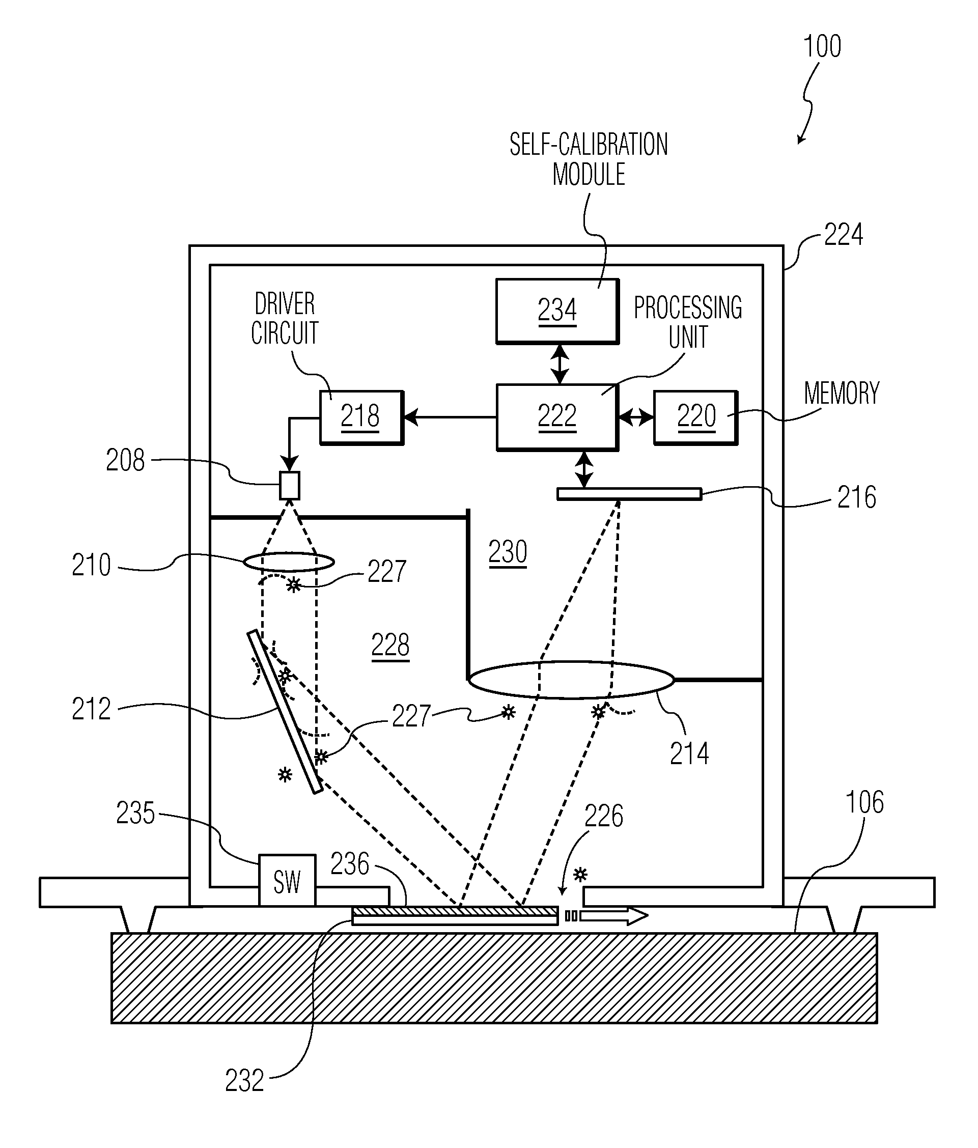
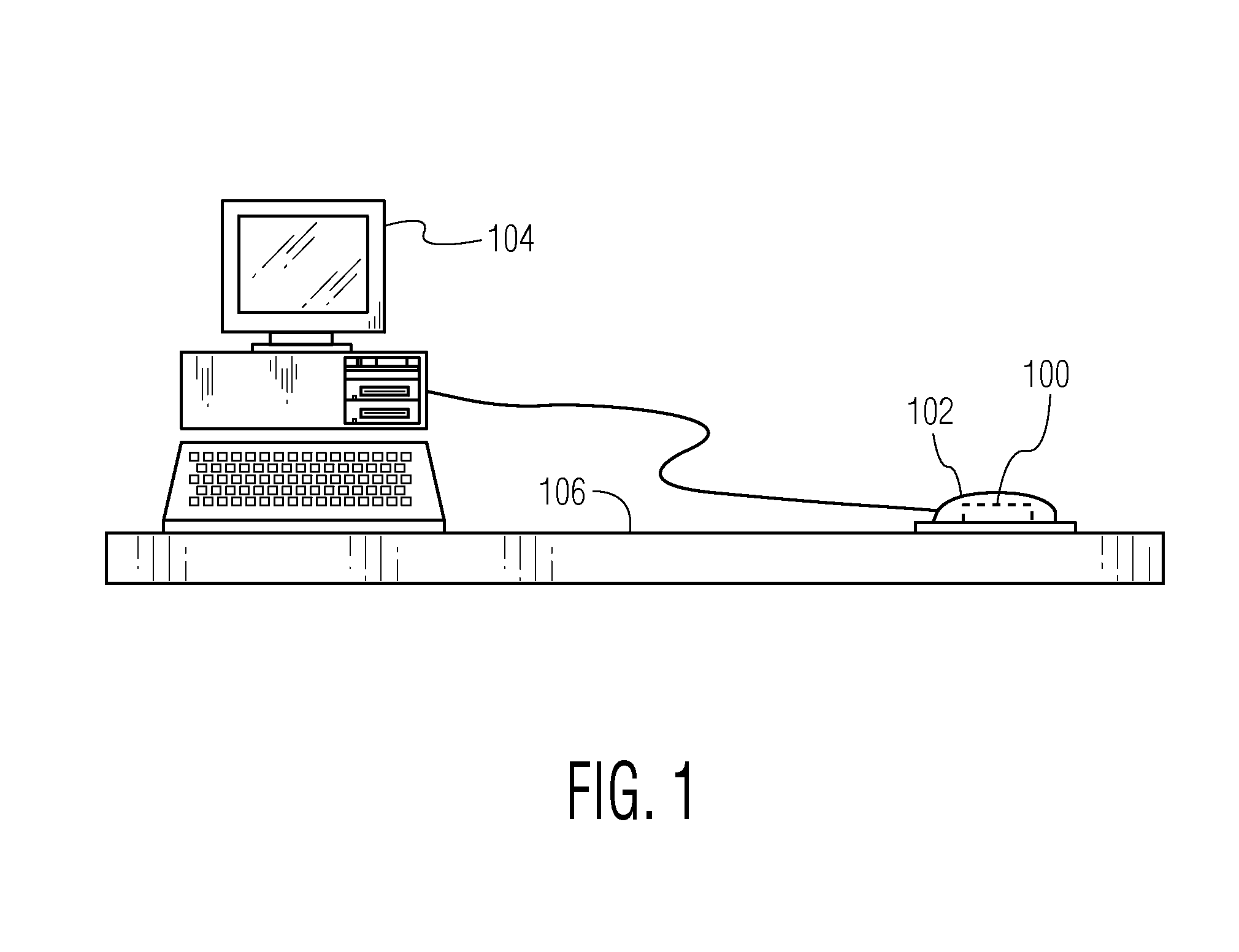
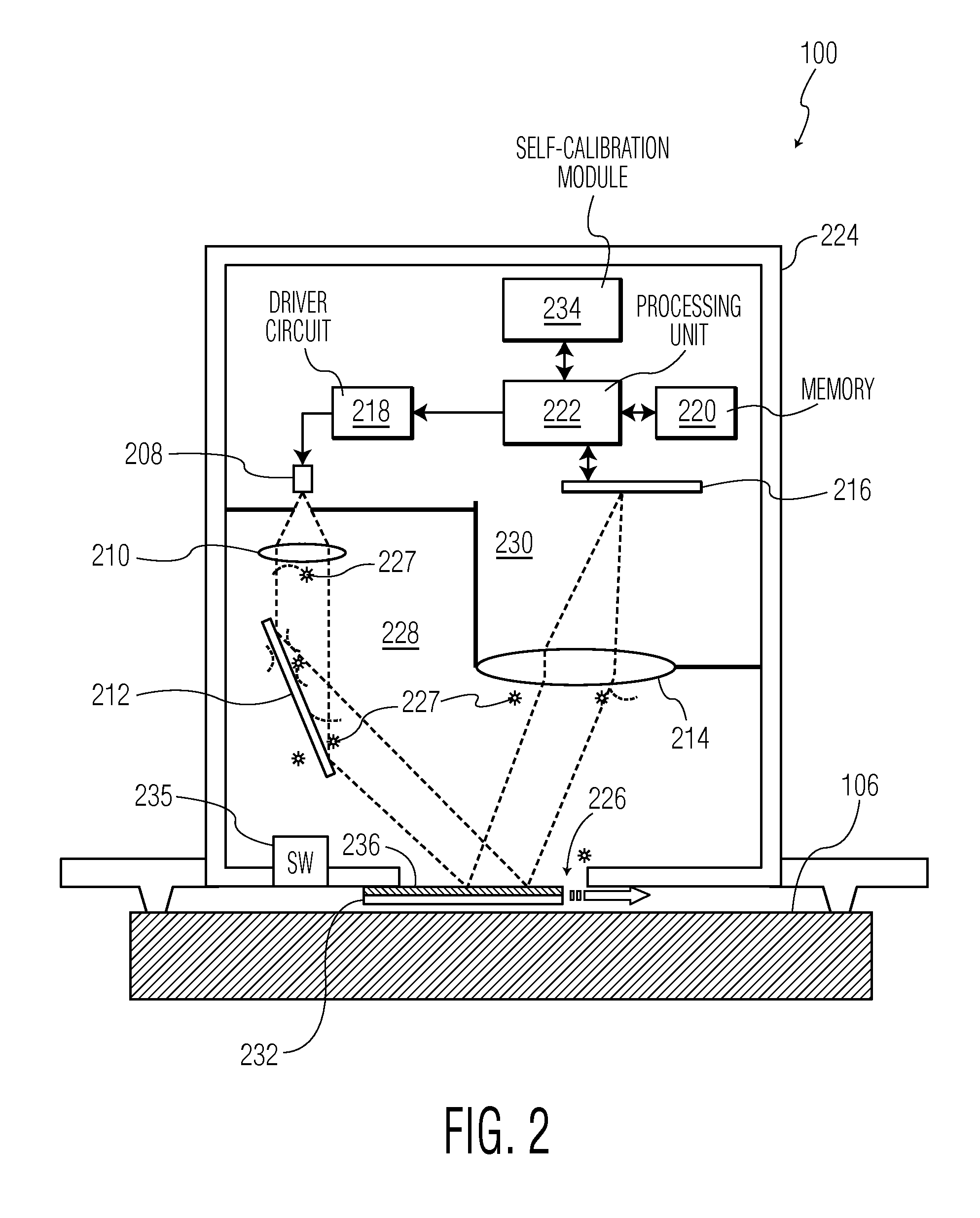
[0017]With reference to FIG. 1, an optical navigation system 100 in accordance with an embodiment of the invention is shown. As shown in FIG. 1, the optical navigation system 100 is included in an optical computer mouse 102, which is connected to a computer 104. In this implementation, the optical navigation system 100 is used to track the movements of the optical mouse 102 as the optical mouse is manipulated over a navigation surface 106, which can be any type of suitable surface, by a user to control a cursor displayed on the computer 104. However, in other implementations, the optical navigation system 100 can be used in different products for various tracking applications. As described in detail below, the optical navigation system 100 is configured to perform self-calibration using a known surface to detect performance degradation, which may be due to contamination on various components of the system and / or operational deviation of one or more components of the system. Once per...


PUM


Abstract

An optical navigation system and method for performing self-calibration on the system uses captured frames of image data of an interior surface of a calibration cover of the system to detect a performance-related change of the system. In response to the detected performance-related change, a predefined procedure is then initiated.

Description

BACKGROUND OF THE INVENTION[0001]Optical navigation systems operate to estimate movements between the optical navigation systems and navigation surfaces to perform tracking operations. An optical navigation system uses a light source, such as a light-emitting diode (LED) or a laser diode, to illuminate a region of a navigation surface and an image sensor array to receive the light reflected from the navigation surface to successively capture frames of image data of the navigation surface. The optical navigation system compares the successive image frames and estimates the relative movements between the optical navigation system and the navigation surface based on the comparisons between the successive image frames. The comparisons are based on detecting and computing displacements of features in the captured frames of image data, which involve performing cross-correlations on the frames of image data.[0002]Optical navigation systems are commonly used in optical computer mice to trac...

Claims


Application Information

Patent Timeline
Patent Type & Authority Applications(United States)
IPC IPC(8): G06F3/033G01D18/00G06F3/038
CPCG06F3/0317G06F3/0383G06F3/038
Inventor GAO, JUN
Owner PIXART IMAGING INC
Why Eureka
Try Eureka