LED lamp having light guide

a technology of led lamps and light guides, which is applied in the direction of instrumentation, lighting and heating apparatus, planar/plate-like light guides, etc., can solve the problems of increasing the thickness and accordingly the volume of the lamp, and the volume of the conventional lamp cannot be small

Inactive Publication Date: 2011-06-23
FU ZHUN PRECISION IND SHENZHEN +1
View PDF3 Cites 67 Cited by
  • Summary
  • Abstract
  • Description
  • Claims
  • Application Information

AI Technical Summary

Benefits of technology

[0004]LEDs, available since the early 1960's and because of their high light-emitting efficiency, have been increasingly used in a variety of occasions, such as residential, traffic, commercial, and industrial occasions. In order to obtain a surface light emission, conventional direct-type LED lamp generally uses a diffusion plate cooperating with the spot light source, i.e., the LEDs thereof. The diffusion plate is often placed to face the LEDs, thereby to scatter the light emitted from the LEDs. By adjusting the distance between the LEDs and the diffusion plate, the light output from the lamp can be modulated to be smooth and uniform. However, the conventional lamp needs sufficient distance left between the LEDs and the diffusion plate to produce the smooth and uniform surface light emission, causing increasing in thickness and accordingly volume of the lamp. Thus, the conventional lamp cannot have a small volume.

Problems solved by technology

However, the conventional lamp needs sufficient distance left between the LEDs and the diffusion plate to produce the smooth and uniform surface light emission, causing increasing in thickness and accordingly volume of the lamp.
Thus, the conventional lamp cannot have a small volume.

Method used


Image

  • LED lamp having light guide
  • LED lamp having light guide
  • LED lamp having light guide

Examples


Embodiment Construction

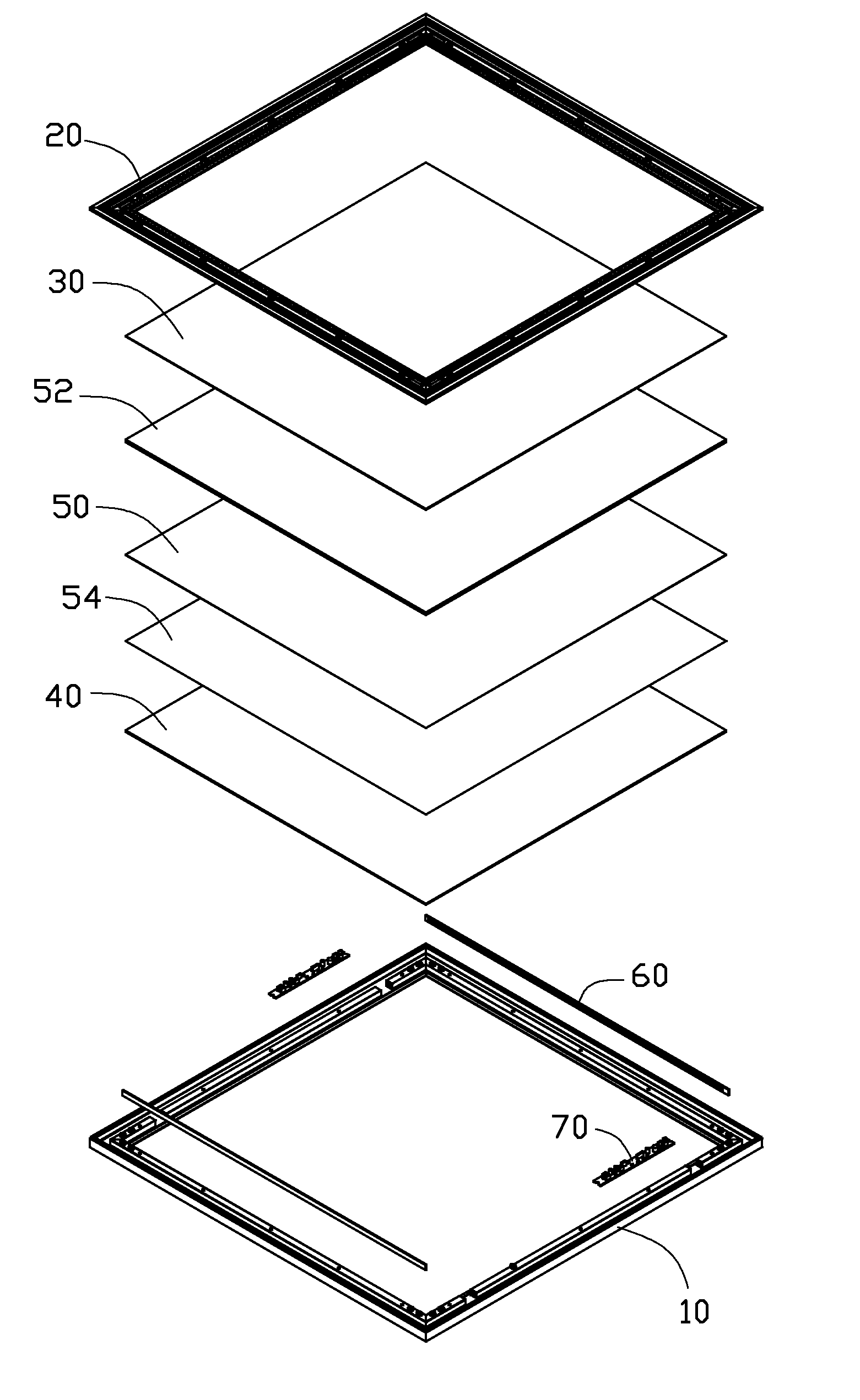
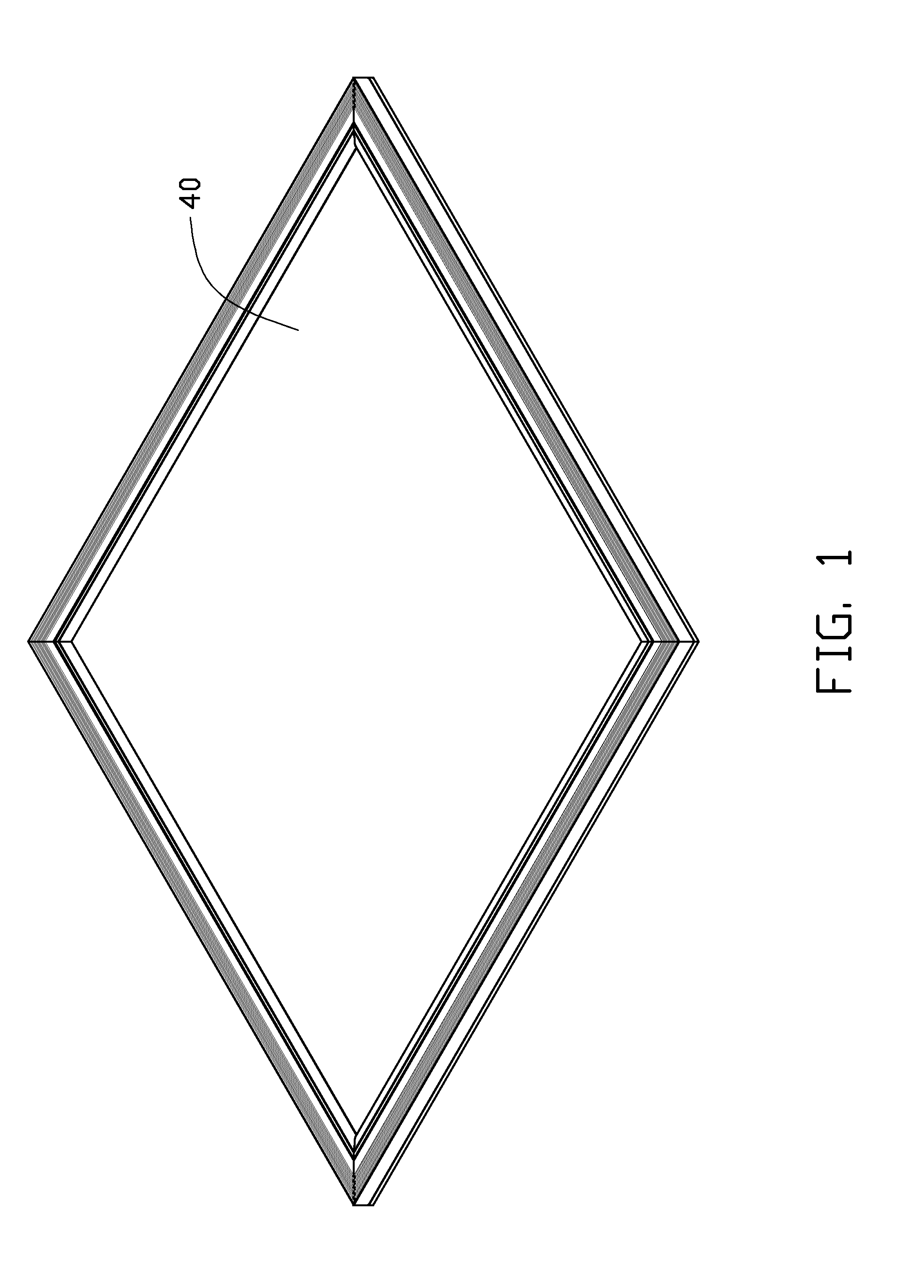
[0016]Referring to FIGS. 1-4, an LED lamp of the present disclosure is illustrated. The LED lamp includes a frame 10, a bracket 20 connected to the frame 10, a backplate 30 fixed in the bracket 20, a cover 40 fixed in the frame 10, a diffusion plate 54, a light guide 50 and a reflective plate 52 sandwiched between the backplate 30 and the cover 40, and two LED modules 60 and driving modules 70 received between the frame 10 and bracket 20.

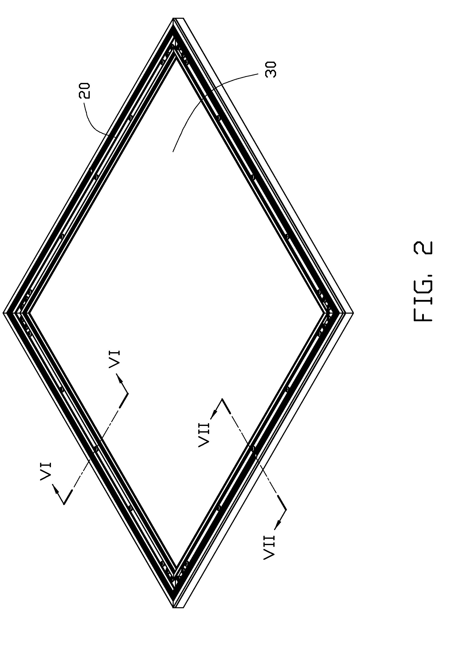
[0017]Also referring to FIGS. 5-7, the frame 10 includes four beams 100 connected to each other by four L-shaped connectors 18 to form a square configuration. Each beam 100 includes a pressing portion 12, a locking portion 16 and a supporting portion 14 interconnecting the pressing portion 12 and the locking portion 16. The supporting portion 14 is upwardly protruded and has a hollow rectangular cross-section. The supporting portion 14 supports the bracket 20 thereon. The pressing portion 12 extends inwardly and horizontally from a bottom of the sup...


PUM


Abstract

An LED lamp includes a frame, a bracket connected to the frame, two LED modules and driving modules received between the frame and the bracket, and a backplate, a reflective plate, a light guide, a diffusion plate and a cover sequentially sandwiched between the frame and the bracket. The LED modules are oriented towards two opposite lateral sides of the light guide. The light guide has a large amount of scattering dots formed on a back face thereof. The scattering dots are arranged in multiple columns. The sizes of the dots in each column are identical to each other, and the sizes of the dots in different columns gradually increase from two opposite sides towards a middle of the light guide.

Description

BACKGROUND[0001]1. Technical Field[0002]The present disclosure relates to light emitting diode (LED) lamps and, more particularly, to an LED lamp having a small thickness by use of a light guide.[0003]2. Description of Related Art[0004]LEDs, available since the early 1960's and because of their high light-emitting efficiency, have been increasingly used in a variety of occasions, such as residential, traffic, commercial, and industrial occasions. In order to obtain a surface light emission, conventional direct-type LED lamp generally uses a diffusion plate cooperating with the spot light source, i.e., the LEDs thereof. The diffusion plate is often placed to face the LEDs, thereby to scatter the light emitted from the LEDs. By adjusting the distance between the LEDs and the diffusion plate, the light output from the lamp can be modulated to be smooth and uniform. However, the conventional lamp needs sufficient distance left between the LEDs and the diffusion plate to produce the smoo...

Claims


Application Information

Patent Timeline
Patent Type & Authority Applications(United States)
IPC IPC(8): F21V7/04
CPCG02B6/0043G02B6/0091G02B6/0073
Inventor LV, JIA-CHUANCHEN, CHIN-CHUNGMO, CI-JIN
Owner FU ZHUN PRECISION IND SHENZHEN
Why Eureka
Try Eureka