Power conversion apparatus

Active Publication Date: 2011-06-23
YASKAWA DENKI KK
View PDF3 Cites 27 Cited by
  • Summary
  • Abstract
  • Description
  • Claims
  • Application Information

AI Technical Summary

Benefits of technology

[0008]According to one aspect of the present invention, a power conversion apparatus includes two power conversion circuits that are respectively connected in parallel to a direct-current load (or single-phase alternating-current load) and a three-phase alternating-current load; two direct-current inductors; and a pulse-width-modulation (PWM) control circuit that pulse-width-modulates the two power conversion ci

Problems solved by technology

The static Leonard system has general technical problems, such as low power factor

Method used


Image

  • Power conversion apparatus
  • Power conversion apparatus
  • Power conversion apparatus

Examples


first embodiment

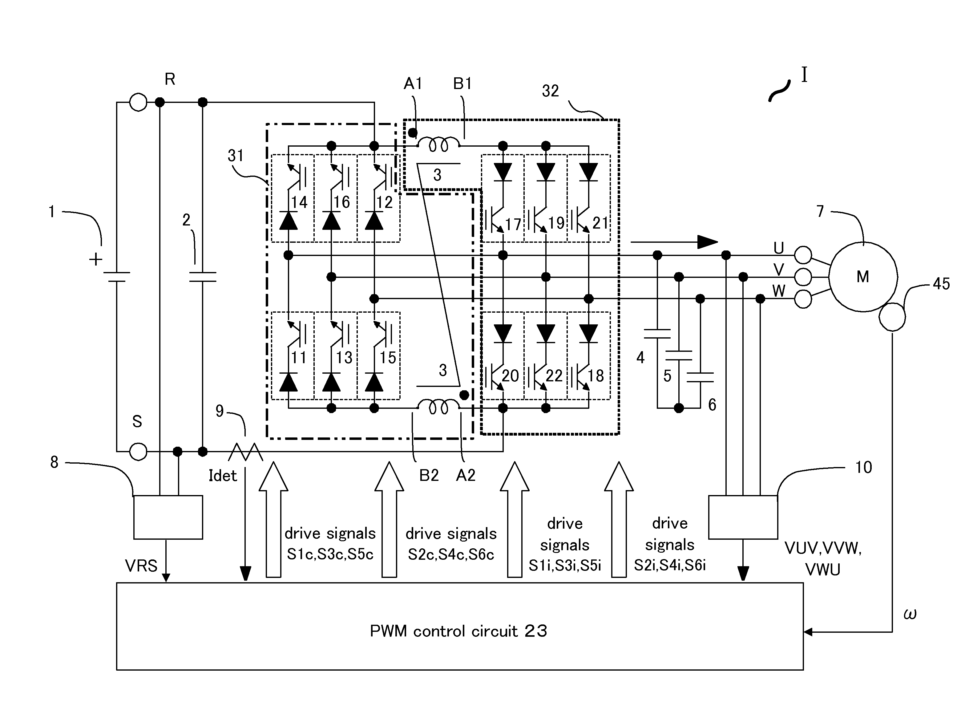
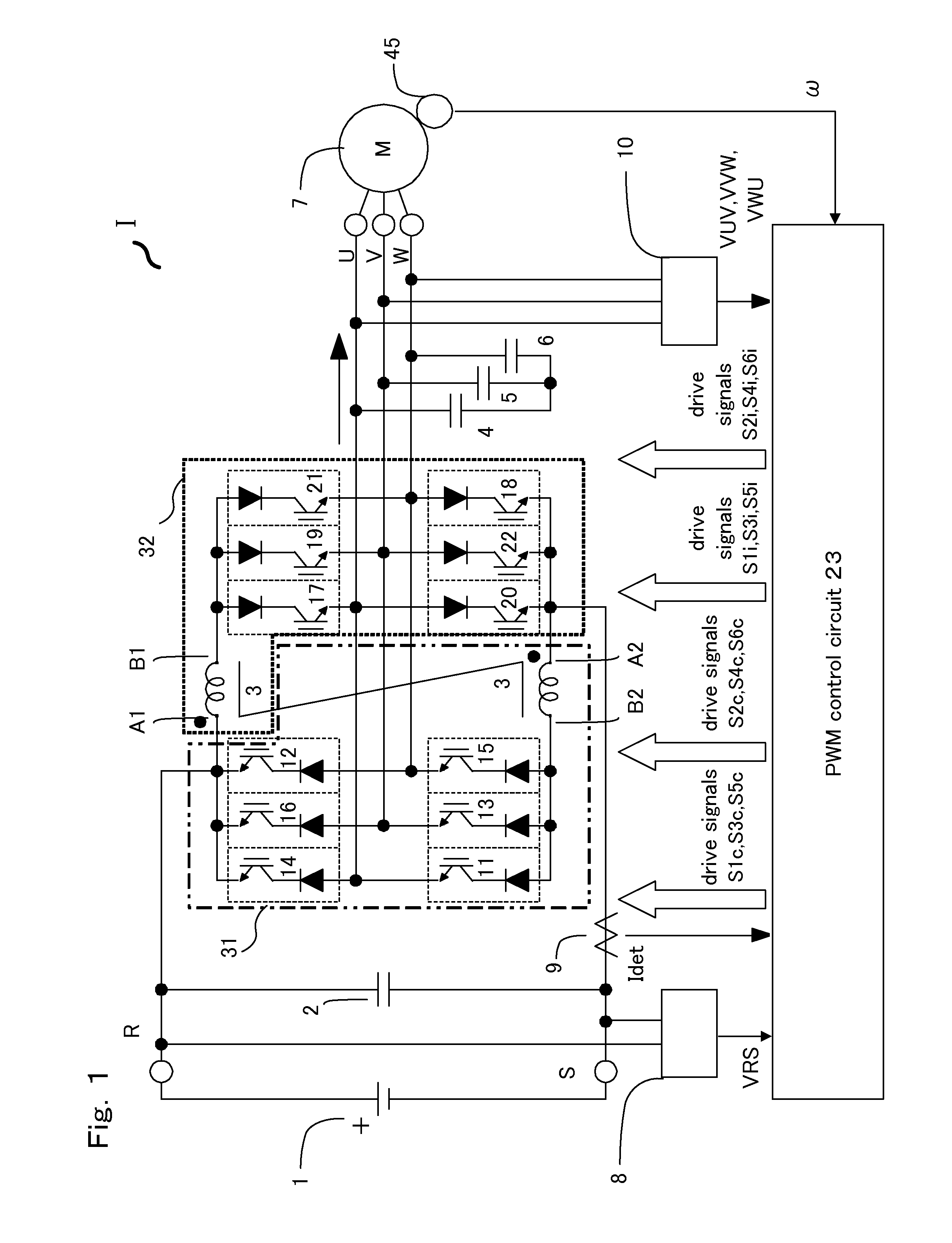
[0023]FIG. 1 is a block diagram illustrating a power conversion apparatus I according to the present invention.

[0024]The power conversion apparatus I includes a storage battery (hereinafter simply referred to as “battery”) 1; capacitors 2, 4, 5, and 6; a coupled inductor 3; an electric motor (hereinafter simply referred to as “motor”) 7; voltage detectors 8 and 10; a current detector 9; a PWM control circuit 23; a first power conversion circuit 31; a second power conversion circuit 32; and a speed detector 45.

[0025]The battery 1 serves as a direct-current load, and the motor 7 serves as a three-phase alternating-current load.

[0026]The coupled inductor 3 has a first winding and a second winding. The speed detector 45 detects a speed of the motor 7.

[0027]The PWM control circuit 23 pulse-width-modulates the first power conversion circuit 31 and the second power conversion circuit 32.

[0028]The first power conversion circuit 31 and the second power conversion circuit 32 are current-type ...


PUM


Abstract

A power conversion apparatus includes two power conversion circuits, two direct-current inductors, and a pulse-width-modulation control circuit. One of the two power conversion circuits is connected in parallel to a direct-current load or a single-phase alternating-current load, and the other of the two power conversion circuits is connected in parallel to a three-phase alternating-current load. The two power conversion circuits are connected in reverse polarity to each other via the two direct-current inductors. The pulse-width-modulation control circuit pulse-width-modulates the two power conversion circuits, allows switching between the two power conversion circuits, and realizes a bidirectional step-up/down operation between the direct-current load or single-phase alternating-current load and the three-phase alternating-current load.

Description

CROSS-REFERENCE TO RELATED APPLICATION[0001]The present application claims priority under 35 U.S.C. §119 to Japanese Patent Application No. 2009-291114, filed Dec. 22, 2009. The contents of the application are incorporated herein by reference in their entirety.BACKGROUND OF THE INVENTION[0002]1. Field of the Invention[0003]The present invention relates to power conversion apparatuses.[0004]2. Description of Related Art[0005]A static-Leonard power conversion apparatus using thyristors is capable of performing a step-up / down operation based on bidirectional conversion between direct current or single-phase alternating current and three-phase alternating current, and of performing rapid switching between acceleration and regeneration. The static Leonard system has general technical problems, such as low power factor caused by phase control of thyristors and low efficiency caused by cyclic currents.[0006]Japanese Unexamined Patent Application Publication No. 2005-269735 discloses a vehi...

Claims


Application Information

Patent Timeline
IPC IPC(8): H02M7/758
CPCH02M5/4585
Inventor YAMANAKA, KATSUTOSHI
Owner YASKAWA DENKI KK
Why Eureka
Try Eureka