

Optical wiring cable
a technology of optical wiring and optical cable, applied in the field of optical wiring cables, can solve the problems of electromagnetic noise malfunction, the speed limit of the electrical wire connecting the lsis, and the problem of lsis connecting with the speed limit, and achieve the effect of realizing the problem
- Summary
- Abstract
- Description
- Claims
- Application Information
AI Technical Summary
Problems solved by technology
Method used
Image

Examples
first embodiment
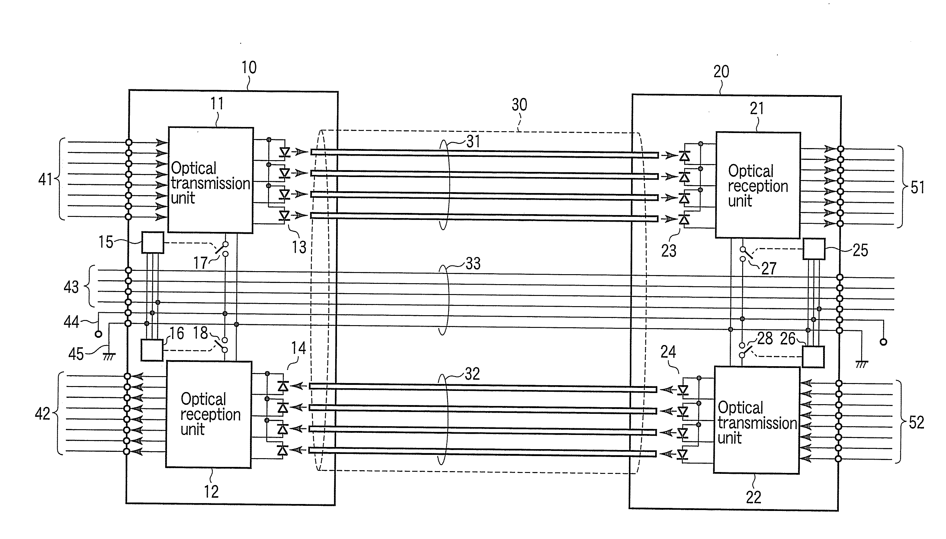
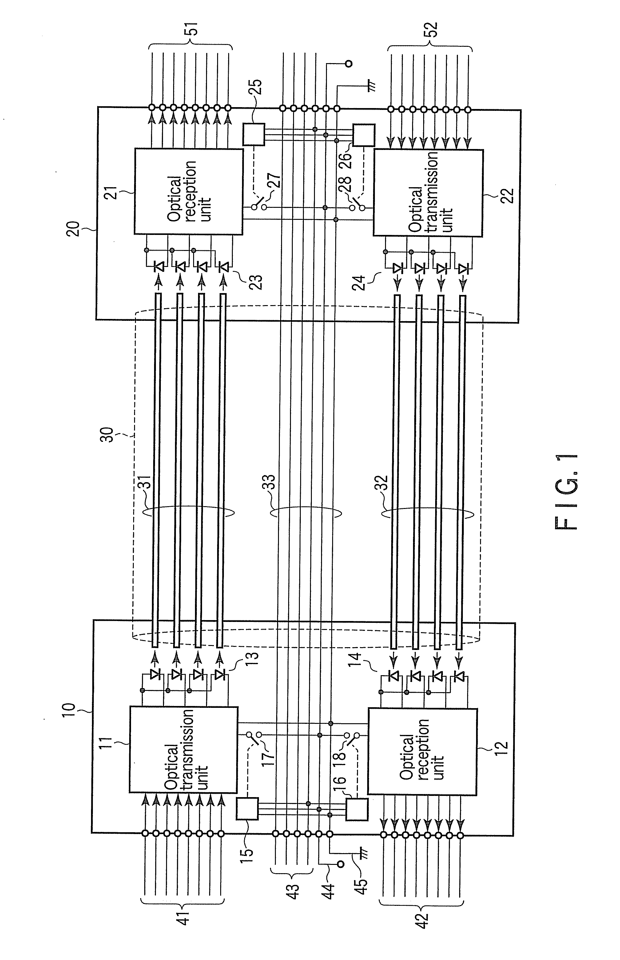
FIG. 1 is a schematic configuration diagram showing an optical wiring cable according to a first embodiment.
This device is constituted of a first connector 10, second connector 20, and optoelectronic interconnection 30 connecting these connectors 10 and 20 to each other.
The optoelectronic interconnection 30 includes a plurality of first optical interconnection paths 31 configured to transmit an optical signal from the first connector 10 to the second connector 20, a plurality of second optical interconnection paths 32 configured to transmit an optical signal from the second connector 20 to the first connector 10, and electrical wires 33 configured to electrically connect the first and second connectors 10 and 20 to each other. Each of the optical interconnection paths 31 and 32 is constituted of an optical fiber, optical waveguide or the like.
In the first connector 10, an optical transmission unit (first optical transmission unit) 11 configured to transmit an optical signal to the f...
second embodiment
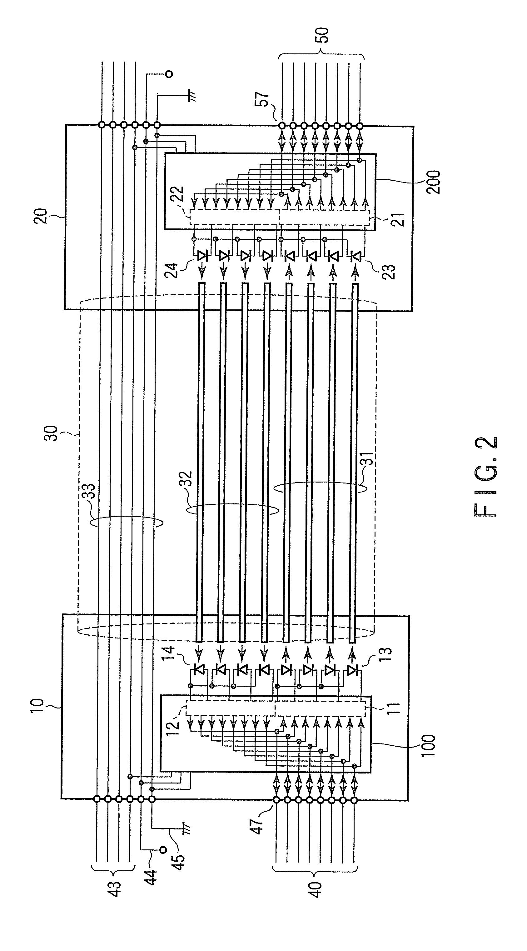
FIG. 2 is a schematic configuration diagram showing an optical wiring cable according a second embodiment. It should be noted that the same parts as those in FIG. 1 are denoted by the same reference symbols as those in FIG. 1, and a detailed description of them will be omitted.
The second embodiment is an example premised on a case where bidirectional transmission is not simultaneously carried out in the first embodiment. In FIG. 2, a reference symbol 40 denotes data signal lines (high-speed signal lines) connected to electrical input / output terminals 47 of a connector 10, reference symbol 50 denotes data signal lines (high-speed signal lines) connected to electrical input / output terminals 57 of a connector 20, and reference symbols 100 and 200 denote optical transmission / reception units each containing an optical transmission unit, and optical reception unit.
FIG. 3 is a view showing an example of the specific configuration of an optical transmission / reception unit 100 on the connect...
third embodiment
FIG. 5 is a schematic configuration diagram showing an optical wiring cable according to a third embodiment. It should be noted that the same parts as those in FIG. 2 are denoted by the same reference symbols as FIG. 2, and a detailed description of them will be omitted. This embodiment is an example premised on the case where simultaneous bidirectional transmission is not carried out as in the second embodiment.
This embodiment differs from the second embodiment in that control signal lines 43 are not connected between the connector 10 and connector 20 by electrical wires 33, but are data-superposed on an optical signal to be transmitted by the optical interconnection paths 31 and 32.
FIG. 6 is a view showing an example of the specific configuration of an optical transmission / reception unit 100 of FIG. 5. The optical transmission / reception unit 100 includes optical transmission units 11 (11a to 11d), optical reception units 12 (12a to 12d), and switches 17 (17a to 17d), and 18 (18a t...
PUM
 Abstract
Description
Claims
Application Information