
Enhanced visual landmark for localization

a visual landmark and localization technology, applied in the field of mobile robotic navigation, can solve the problems of physical perimeters presenting challenges, ineffective during low-light or no-light conditions,

Active Publication Date: 2011-06-23
DEERE & CO
View PDF99 Cites 19 Cited by
  • Summary
  • Abstract
  • Description
  • Claims
  • Application Information

AI Technical Summary

Benefits of technology

[0004]The different illustrative embodiments provide a localization apparatus comprising an identification signal and an orientation controller. The identification signal is for recognition by a localized machine for utilizing t

Problems solved by technology

Visual landmarks may operate to reflect light for detection by a robotic navigation system, but may be ineffective during low-light or no-light conditions, such as night time.
However, physical perimeters present a challenge when a sidewalk or driveway must be traversed to access a worksite, for example.

Method used


Image

  • Enhanced visual landmark for localization
  • Enhanced visual landmark for localization
  • Enhanced visual landmark for localization

Examples


Embodiment Construction

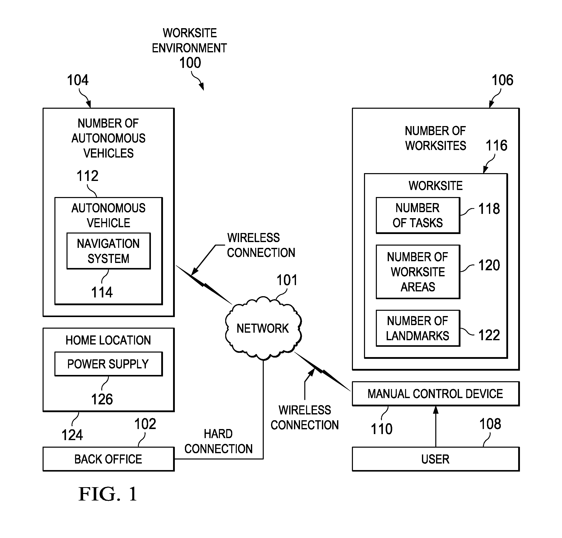
[0015]With reference to the figures and in particular with reference to FIG. 1, a block diagram of a worksite environment is depicted in which an illustrative embodiment may be implemented. Worksite environment 100 may be any type of worksite environment in which a localized machine can operate. A localized machine may be any type of machine with at least one function performed automatically based on a position of the machine. Functions include, but are not limited to, guidance, material application, and data collection. A localized machine may be, for example, without limitation, an autonomous vehicle. In an illustrative example, worksite environment 100 may be a structure, building, worksite, area, yard, golf course, indoor environment, outdoor environment, different area, change in the needs of a user, and / or any other suitable worksite environment or combination of worksite environments.

[0016]As an illustrative example, a change in the needs of a user may include, without limita...


PUM


Abstract

The different illustrative embodiments provide a localization apparatus comprising an identification signal and an orientation controller. The identification signal is for recognition by a localized machine for utilizing the localization apparatus as a location point. The orientation controller is configured to control an orientation of the identification signal dependent upon an orientation of the localization apparatus in a defined environment.

Description

CROSS REFERENCE TO RELATED APPLICATIONS[0001]This application is related to commonly assigned and co-pending U.S. patent application Ser. No. ______ (Attorney Docket No. 18835-US) entitled “System and Method for Area Coverage Using Sector Decomposition”; U.S. patent application Ser. No. ______ (Attorney Docket No. 18885-US) entitled “System and Method for Deploying Portable Landmarks” all of which are hereby incorporated by reference.FIELD OF THE INVENTION[0002]The present invention relates generally to systems and methods for navigation and more particularly to systems and methods for mobile robotic navigation. Still more specifically, the present disclosure relates to an enhanced visual landmark for robotic localization.BACKGROUND OF THE INVENTION[0003]The use of robotic devices to perform physical tasks has increased in recent years. Mobile robotic devices can be used to perform a variety of different tasks. These mobile devices may operate in semi-autonomous or fully autonomous ...

Claims


Application Information

Patent Timeline
IPC IPC(8): G06F19/00
CPCG01S5/16G01S1/70G05D1/0234
Inventor ANDERSON, NOEL WAYNE
Owner DEERE & CO
Learn More