Small hand-operated sprayer

a hand-operated, sprayer technology, applied in the direction of liquid handling, instruments, closures using stoppers, etc., can solve the problems of easy loss of caps, additional troublesome removal process, and problem of conventional small hand-operated sprayers

Inactive Publication Date: 2011-06-30
CHONG WOO
View PDF11 Cites 9 Cited by
  • Summary
  • Abstract
  • Description
  • Claims
  • Application Information

AI Technical Summary

Benefits of technology

[0012]When the sprayer is activated, the nozzle can spray content pumped from the container to a desired location without being restricted by the locking device since the locking device is located at the rotational coupling portion of the trigger and the main body.
[0024]The shape of the operating portion of the locking device is not particularly limited, provided that the user can easily depress the operating portion. For example, a part of the operating portion which is exposed from the main body may be formed in a horizontal semicircular shape (i.e., a semicircular shape when viewed from above) such that the user can easily depress the operating portion by their finger.

Problems solved by technology

However, this conventional small hand-operated sprayer can be problematic in that content is dispensed as soon as the trigger is depressed.
However, this requires an additional troublesome process of removing and replacing the cap when the sprayer is used.
In addition, the cap is easily lost.
However, when the sprayer is activated after the cap is detached, the cap may obstruct spraying since the cap is located near the nozzle.
Although small hand-operated sprayers having various structures have been developed to overcome such problems, there is currently no practical small hand-operated sprayer that provides satisfactory results.

Method used


Image

  • Small hand-operated sprayer
  • Small hand-operated sprayer
  • Small hand-operated sprayer

Examples


Embodiment Construction

[0037]Embodiments of the present invention will be described with reference to the drawings. However, it should be noted that the description of the embodiments is given only for better understanding of the present invention and the scope of the present invention is not limited by the embodiments.

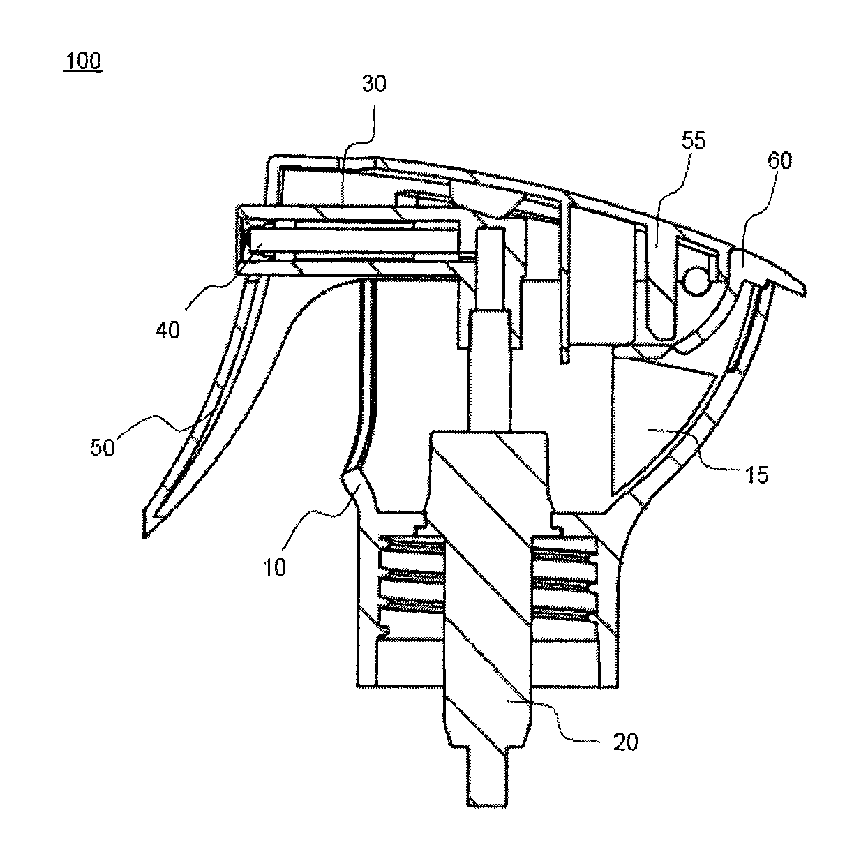
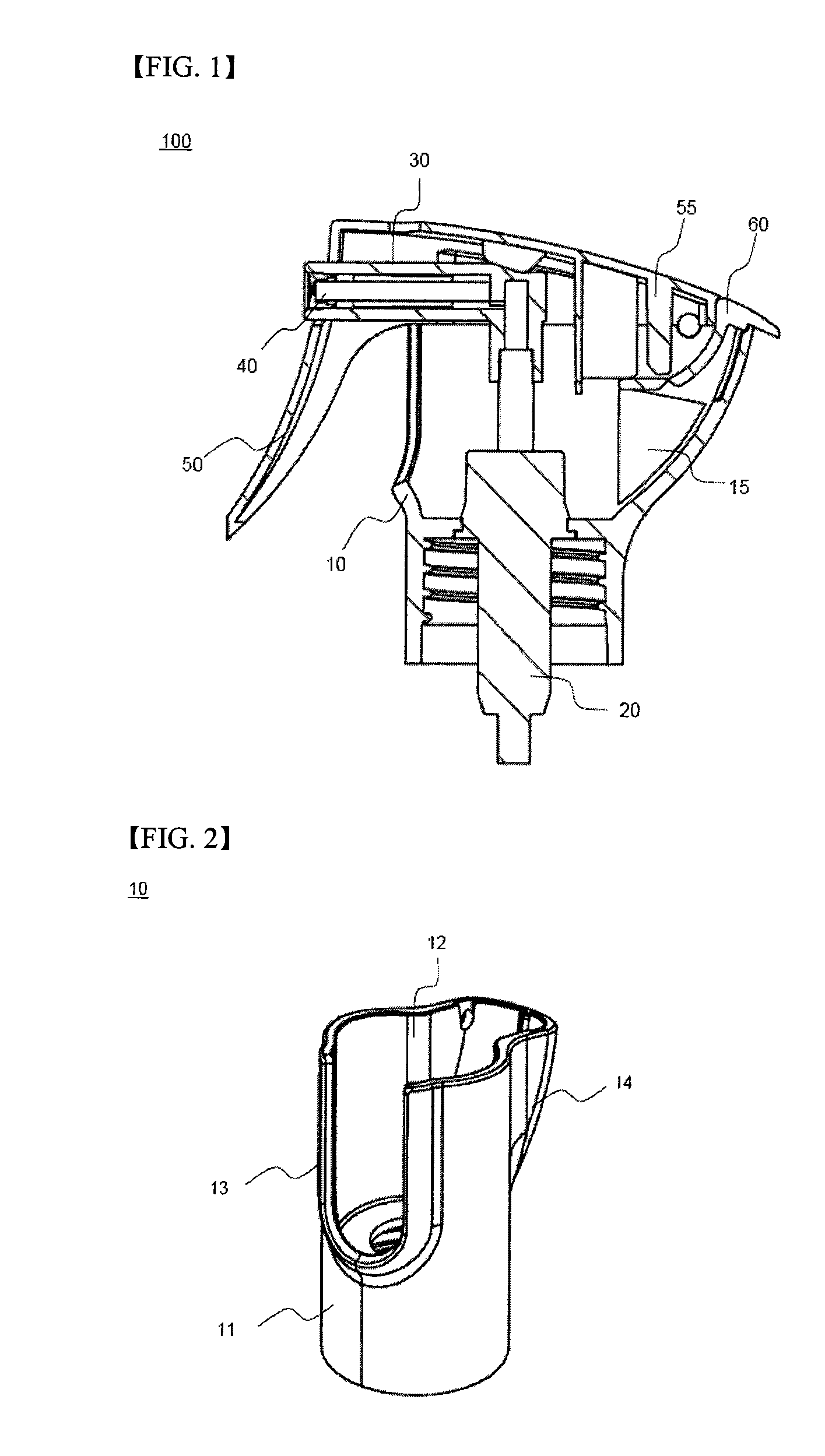
[0038]FIG. 1 is a schematic cross-sectional view of a small hand-operated sprayer according to an embodiment of the present invention.

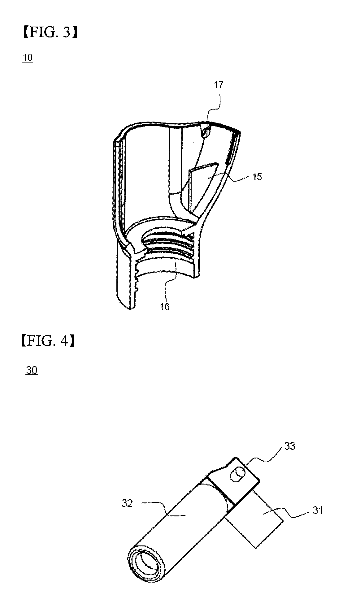
[0039]As shown in FIG. 1, the small hand-operated sprayer 100 includes a main body 10, a hand-operated pump 20, a button 30, a spray nozzle 40, a trigger 50, and a locking device 60. The main body 10 forms the exterior of the small hand-operated sprayer 100 and is coupled to the top of a container (not shown) that holds content. The hand-operated pump 20 is mounted inside the main body 10 and pumps content out of the container through up-and-down movement of the button 30. The button 30 has a hollow structure and is mounted on the top of the hand-operated pum...


PUM


Abstract

A small hand-operated sprayer for spraying small volumes of content is provided. The sprayer includes a main body forming an exterior of the sprayer, the main body being coupled to a top of a container that holds content, a hand-operated pump mounted inside the main body to pump content out of the container through up-and-down movement of a button, the button having a hollow structure mounted on top of the hand-operated pump such that the button communicates with the hand-operated pump, the button including a vertical channel communicating with the hand-operated pump and a horizontal channel extending from the vertical channel, a spray nozzle mounted in the horizontal channel in the button, a trigger having one side at which a front end portion of the button including the spray nozzle is exposed and an opposite side that is rotatably coupled to the main body such that the trigger presses the button downward when a handle of the trigger is pulled and the trigger returns to an original position due to restoring force when the handle is released, and a locking device provided at a rotational coupling portion of the trigger and the main body, the locking device enabling or disabling operation of the trigger with respect to the main body as needed.

Description

TECHNICAL FIELD[0001]The present invention relates to a small hand-operated sprayer for spraying small volumes of content, and more particularly to a small hand-operated sprayer including a main body forming an exterior of the sprayer, the main body being coupled to a top of a container that holds content, a hand-operated pump mounted inside the main body to pump content out of the container through up-and-down movement of a button, the button having a hollow structure mounted on top of the hand-operated pump such that the button communicates with the hand-operated pump, the button including a vertical channel communicating with the hand-operated pump and a horizontal channel extending from the vertical channel, a spray nozzle mounted in the horizontal channel in the button, a trigger having one side at which a front end portion of the button including the spray nozzle is exposed and an opposite side that is rotatably coupled to the main body, and a locking device provided at a rota...

Claims


Application Information

Patent Timeline
Patent Type & Authority Applications(United States)
IPC IPC(8): B05B11/00B05B15/00G01F11/00
CPCB05B11/306B05B11/3057B05B11/106B05B11/1057B05B11/1011
Inventor LEE, CHUNG KEE
Owner CHONG WOO
Why Eureka
Try Eureka