
Flat panel display

a flat panel display and display device technology, applied in the field of flat panel displays, can solve the problems of affecting the display quality and touch detection of the touch display device, and achieve the effects of flat panel, improved structural strength of the lower edge of the display device, and easy depression

Active Publication Date: 2020-07-09
HKC CORP LTD
View PDF0 Cites 0 Cited by
  • Summary
  • Abstract
  • Description
  • Claims
  • Application Information

AI Technical Summary

Benefits of technology

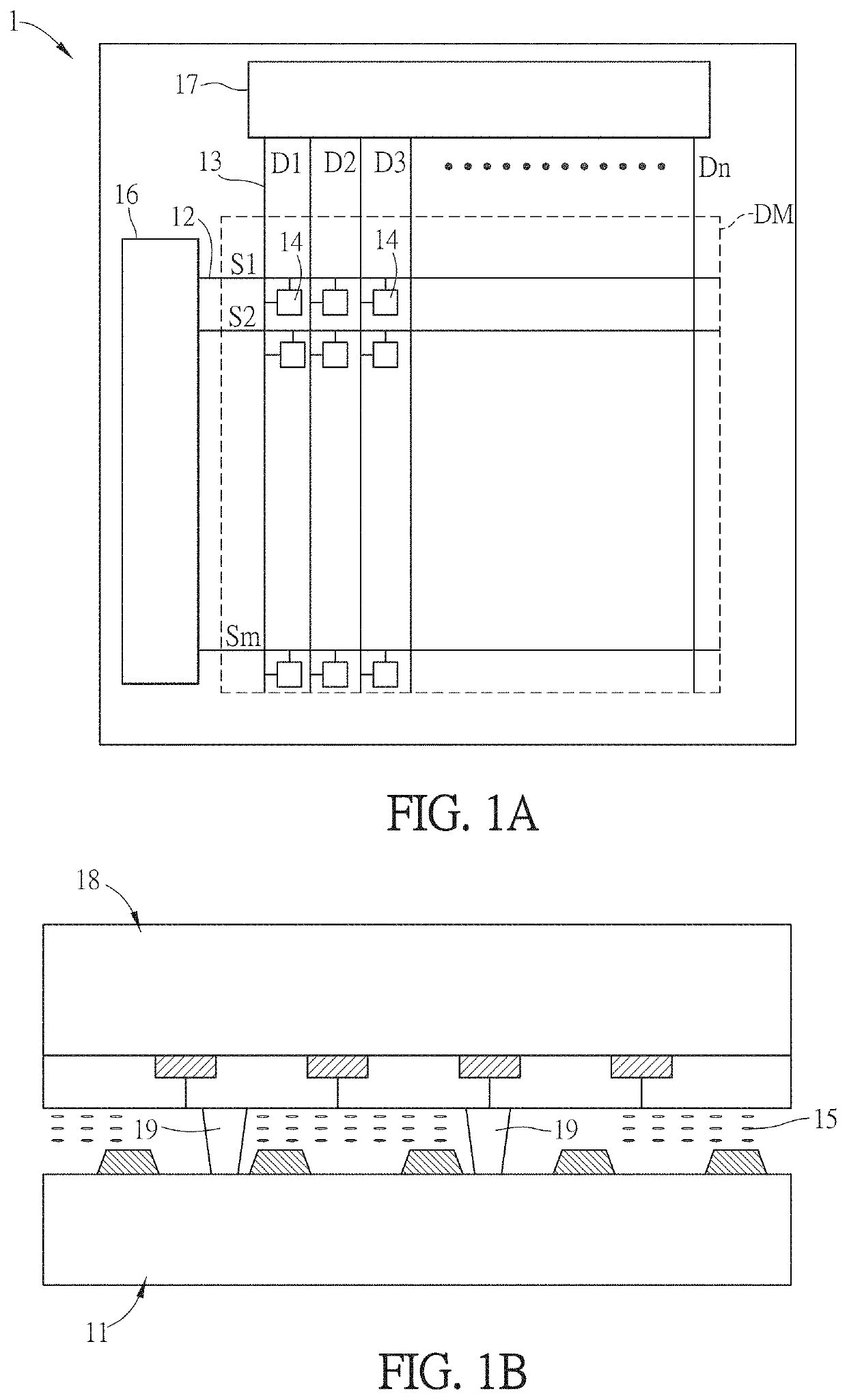
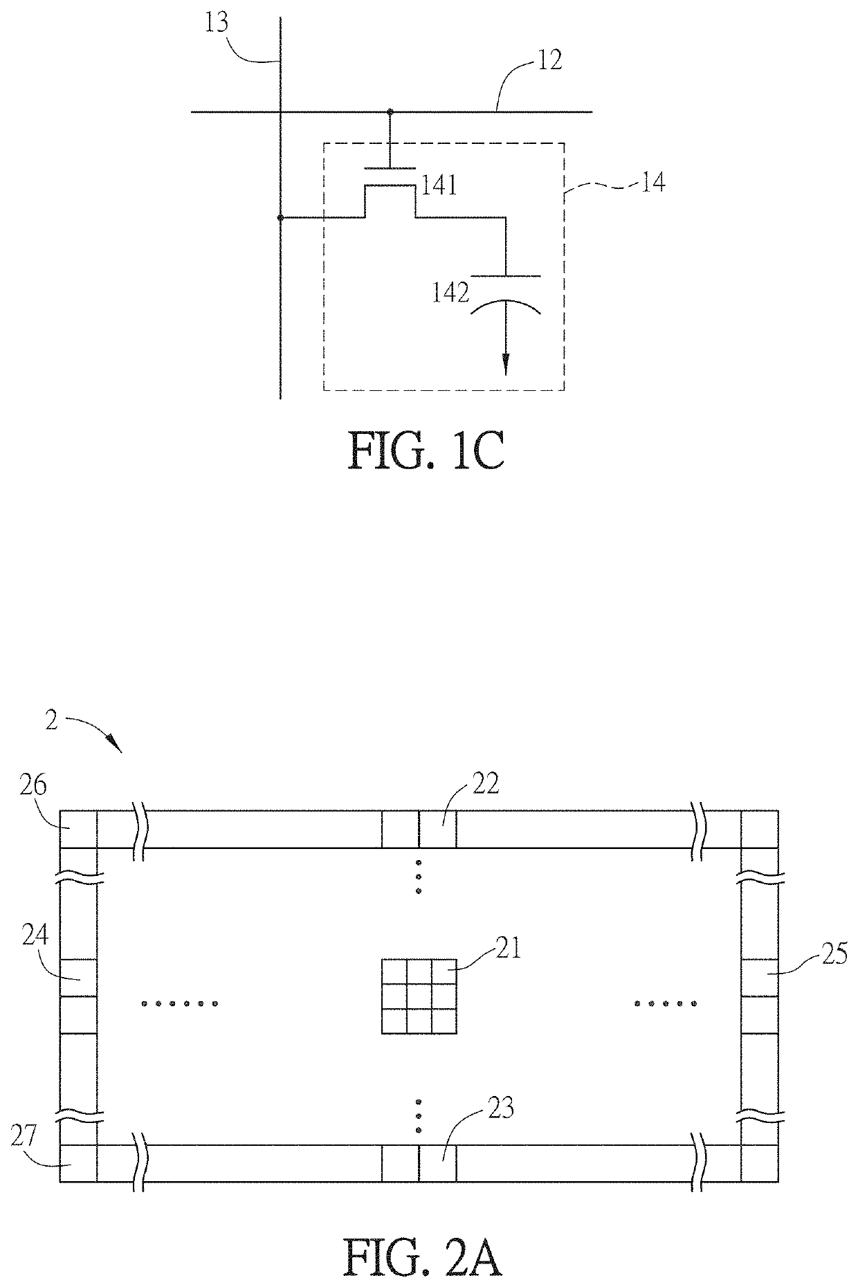
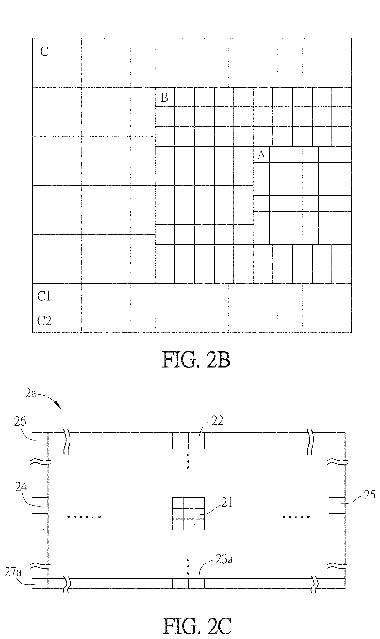
The invention provides a flat panel display with improved distribution of photo spacers and enhanced display efficiency. The display is divided into layout units with the same amount of photo spacers, and the layout unit at the center of the substrate has a larger area than those at the peripheral portions, to solve the problem of easier depression at the center. Moreover, the layout unit at the top edge of one substrate has a larger area than the layout unit at the bottom edge, improving the structural strength of the lower edge of the display device. With this configuration, the non-uniform distribution of photo spacers and production of defective pixels can also be improved.

Problems solved by technology

In addition, the configuration number or method of the photo spacers also affects the display quality, or even the touch detection of the touch display device is affected.

Method used


Image

  • Flat panel display
  • Flat panel display
  • Flat panel display

Examples


Embodiment Construction

[0035]Specific structural and functional details disclosed herein are merely representative and are for purposes of describing example embodiments of the present invention. However, the present invention may be embodied in many alternate forms, and should not be interpreted as being limited to the embodiments set forth herein.

[0036]In the description of the present invention, it is to be understood that the term “center”, “lateral”, “upper”, “lower”, “left”, “right”, “vertical”, “horizontal”, “top”, “bottom”, “inner”, “outer” and other indicated orientation or positional relationships are based on the location or position relationship shown in the drawings, and are for convenience of description of the present invention only and to simplify the description, and not indicate or imply that refers to devices or elements must have a specific orientation, the orientation of a particular configuration and operation, therefore, cannot be construed as limiting the present invention. In addi...


PUM

PropertyMeasurementUnit
voltageaaaaaaaaaa
areaaaaaaaaaaa
areasaaaaaaaaaa

Abstract

A flat panel display is provided. The flat panel display comprises: two substrates disposed opposite each other, a display medium disposed between the substrates, and a photo spacer region where a plurality layout units are distributed, and the layout units are disposed between the substrates. An area of one of the layout units at a central portion of the substrate is larger than an area of another layout unit at a peripheral portion of the substrate.

Description

BACKGROUNDTechnical Field[0001]This disclosure relates to a display device, and more particularly to a flat panel display.Related Art[0002]Flat panel displays have been widely applied to various fields. A liquid crystal display device having the predominant properties, such as the thin and light properties, the low power consumption and the radiationless property, has gradually replaced the conventional cathode ray tube display apparatus, and has been applied to various electronic products, such as a mobile phone, a portable multimedia apparatus, a notebook computer, a liquid crystal television, a liquid crystal display and the like.[0003]The liquid crystal display device comprises elements comprising a display panel. An active matrix type liquid crystal display panel is an ordinary display panel at present and comprises an active matrix substrate, opposing substrates, and a liquid crystal layer disposed between the two substrates. A plurality of row wires, column wires and pixels a...

Claims


Application Information

Patent Timeline
Patent Type & Authority Applications(United States)
IPC IPC(8): G02F1/1339G09G3/36
CPCG02F1/13394G09G3/3688G09G2320/0233G09G3/3648G09G3/20G09G2300/023G09G2300/0426G06F3/0412G02F1/13338G02F2201/40G02F2203/30G06F3/0446G06F3/0416G02F1/133388
Inventor SHAN, JIANFENG
Owner HKC CORP LTD
Learn More