
Lighter

a lighter and piezoelectric technology, applied in the field of lighters, can solve the problems of difficulty for users to light up cigarettes, different engaging mechanisms of cigarette lighters, and heat dissipation, so as to simplify the assembly process of lighters, minimize the necessary components of lighters, and maximize the contact area to the actuating finger

Active Publication Date: 2019-06-27
LUO ZHOU WEN
View PDF0 Cites 0 Cited by
  • Summary
  • Abstract
  • Description
  • Claims
  • Application Information

AI Technical Summary

Benefits of technology

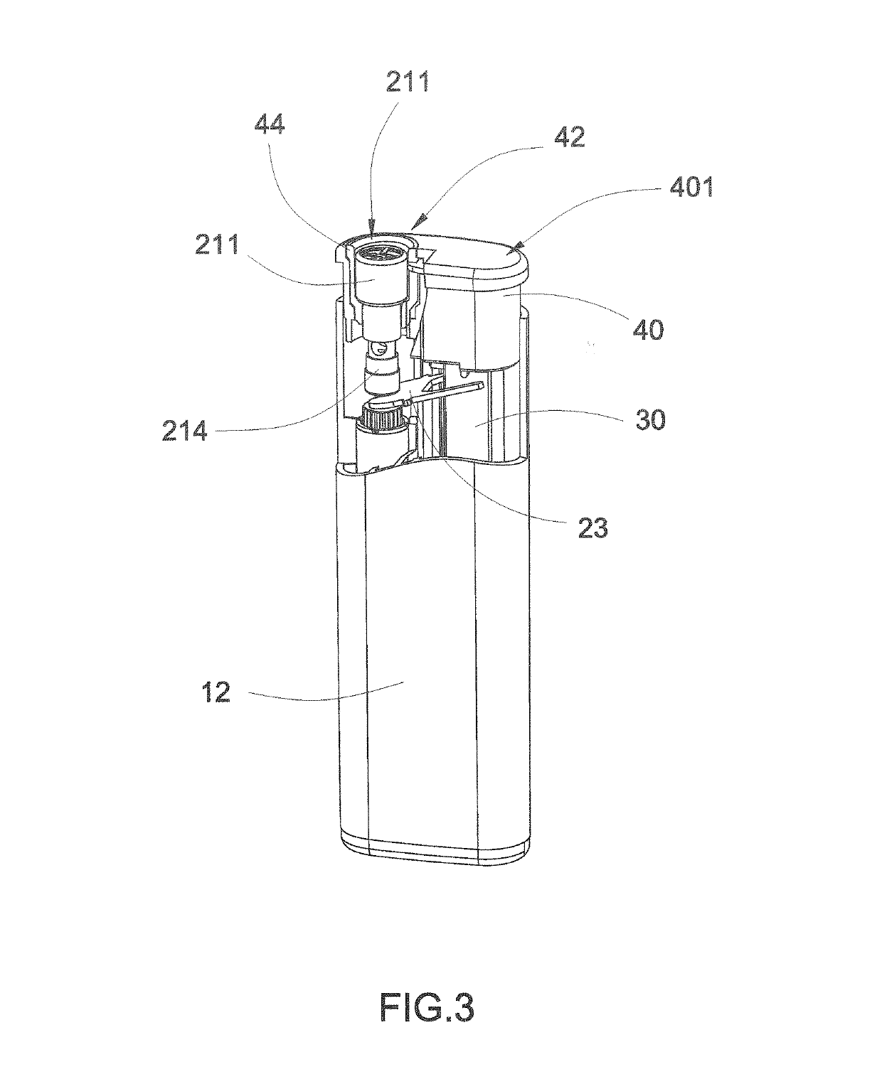
The invention provides a lighter with several technical advantages. It is designed to maximize the contact area between the user's finger and the actuating finger, which reduces the likelihood of accidental ignition. The lighter does not have any ignition button or windshield, which simplifies the assembly process and lowers manufacturing costs. The lighter also has an embedded gas emitting nozzle, which protects it during non-ignition periods. The outgoing portion of the nozzle can protrude at the ignition position, allowing it to also serve as a barbecue lighter. The lighter is also designed to efficiently dissipate heat and has a flat, depressible surface that is easy for users to activate.

Problems solved by technology

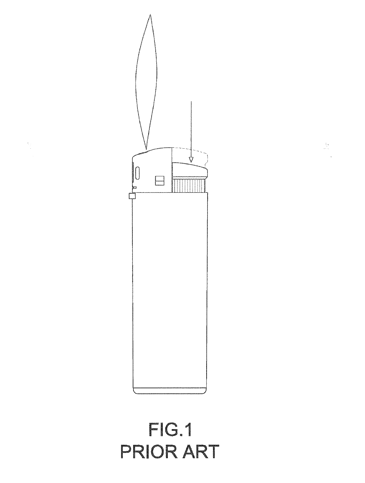
The problem of the existing cigarette lighter is that the cigarette lighter requires different engaging mechanisms to incorporate with different components.
However, since the ignition button is located adjacent to the windshield, the generated flame will heat the windshield and the heat will also dissipate from the windshield to the ignition button that may scald the user's finger.
It is worth mentioning that the flame generated at the exit opening of the gas nozzle will be encircled by the windshield, such that it is difficult for the user to light up a cigarette or the like when the cigarette is positioned away from the exit opening of the gas nozzle.
Another problem of the existing cigarette lighter is that the assembling process thereof is complicated.
If one of the engaging mechanisms is defected, the components cannot be correctly installed and the lighter will not be properly functioned.
In other words, the cigarette lighter may be accidentally ignited or gas leakage during transportation or assembling process by simply actuating the ignition button.

Method used


Image

  • Lighter
  • Lighter
  • Lighter

Examples


Embodiment Construction

[0052]The following description is disclosed to enable any person skilled in the art to make and use the present invention. Preferred embodiments are provided in the following description only as examples and modifications will be apparent to those skilled in the art. The general principles defined in the following description would be applied to other embodiments, alternatives, modifications, equivalents, and applications without departing from the spirit and scope of the present invention.

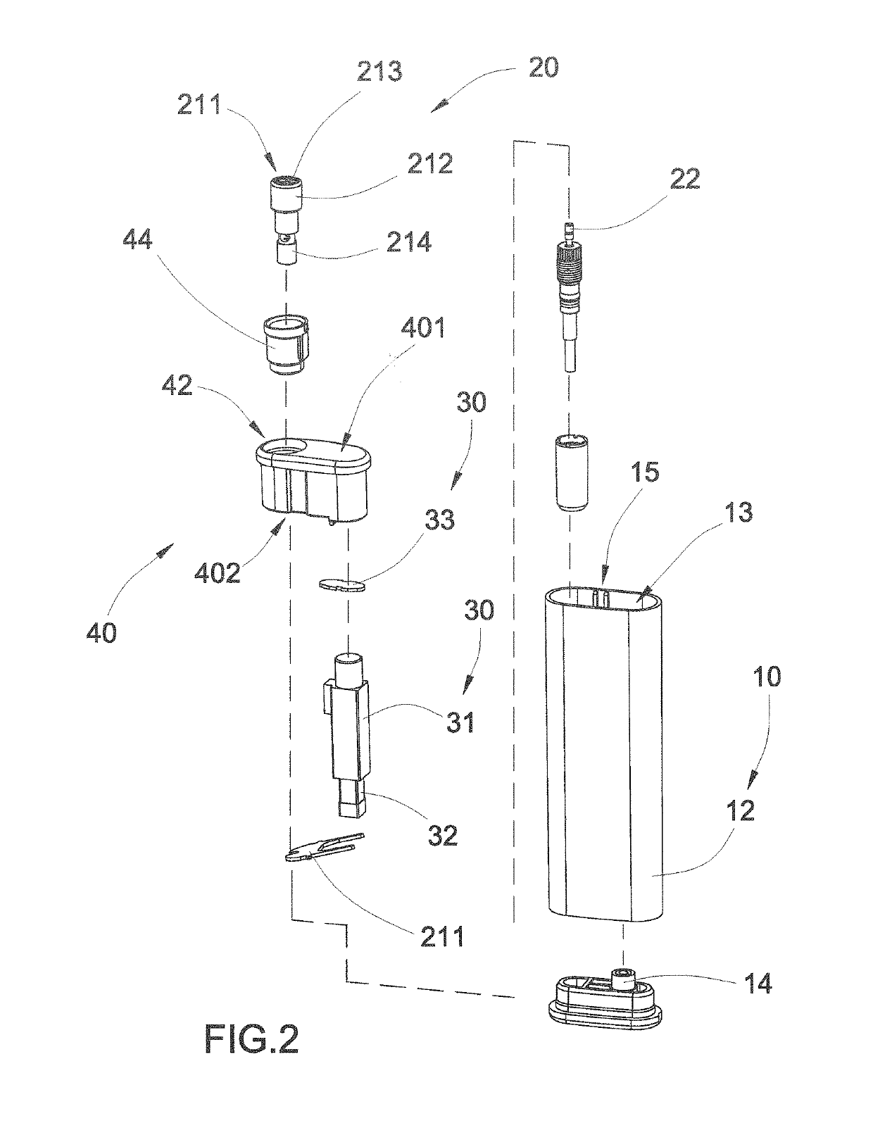
[0053]Referring to FIGS. 2 to 4 of the drawings, a lighter according to a preferred embodiment of the present invention is illustrated, wherein the lighter comprises a lighter housing 10, a gas emission unit 20, a piezoelectric unit 30, and a lighter cap 40.

[0054]The lighter housing 10 has a liquefied gas storage 11. In particular, the lighter housing 10 comprises a casing 12 defining the liquefied gas storage 11 at a bottom portion of the casing 12 and a receiving chamber 13 at an upper portion,...


PUM


Abstract

A piezoelectric lighter includes a lighter housing having a liquefied gas storage, a gas emitting nozzle extended from the liquefied gas storage, a piezoelectric unit disposed in the lighter housing, and a lighter cap slidably coupled on top of the lighter housing above the piezoelectric unit. The gas emitting nozzle is slidably received at a nozzle window of the lighter cap, wherein an exit opening of the gas emitting nozzle is embedded in the ceiling of the lighter cap to protect the exit opening of the gas emitting nozzle. When the lighter cap is depressed to expose the exit opening of the gas emitting nozzle above the ceiling of the lighter cap, the piezoelectric unit is depressed and the gas emission unit is actuated at the same time to produce a flame at the exit opening of the gas emitting nozzle.

Description

CROSS REFERENCE OF RELATED APPLICATION[0001]This is a Continuation application that claims the benefit of priority under 35 U.S.C. § 120 to a non-provisional application, application Ser. No. 15 / 294,780, filed Oct. 16, 2016. The afore-mentioned patent application is hereby incorporated by reference in its entirety.NOTICE OF COPYRIGHT[0002]A portion of the disclosure of this patent document contains material which is subject to copyright protection. The copyright owner has no objection to any reproduction by anyone of the patent disclosure, as it appears in the United States Patent and Trademark Office patent files or records, but otherwise reserves all copyright rights whatsoever.BACKGROUND OF THE PRESENT INVENTIONField of Invention[0003]The present invention relates to a lighter, and more particularly to a piezoelectric lighter which not only avoids the heat of the flame to the user's actuating finger but also minimizes the components of the lighter to simplify the assembling proce...

Claims


Application Information

Patent Timeline
Patent Type & Authority Applications(United States)
IPC IPC(8): F23Q2/28B23P19/00F23Q2/173
CPCF23Q2/287B23P19/00F23Q2/173
Inventor LUO, ZHOU WEN
Owner LUO ZHOU WEN
Learn More