Roof hip and ridge anchor device (CIP)

a technology of ridge anchoring device and roof, which is applied in the direction of snow traps, roofs, transportation and packaging, etc., can solve the problems of inconvenient installation, inability to provide an elongated cover, and inherent limitations of the carrier

Active Publication Date: 2010-08-17
EAST COAST METALS
View PDF26 Cites 14 Cited by
  • Summary
  • Abstract
  • Description
  • Claims
  • Application Information

AI Technical Summary

Benefits of technology

[0009]It is one of the main objects of the present invention to provide a roof hip and ridge attachment device that is compatible with roll forming manufacturing processes while simultaneously providing the mechanical anchorage features to withstand wind forces to which roofs may be exposed.
[0010]It is another object of this invention to provide a device that maximizes the contact area with the adhesive compound with longitudinally extending channels and cooperatively positioned through openings that permit the adhesive compound to go through.
[0011]Another object of the invention is to provide a structure that will cooperate with the adhesive to enhance the engagement of the former with the tile.
[0012]It is yet another object of this invention to provide such a device that is inexpensive to manufacture and maintain while retaining its effectiveness.

Problems solved by technology

Roll forming techniques are suitable for relatively inexpensive production operations but carry inherent limitations.
However, it differs from the present invention because it fails to provide an elongated cover with at least one elongated channel with a coextensive bottom wall and two longitudinally extending walls.

Method used


Image

  • Roof hip and ridge anchor device (CIP)
  • Roof hip and ridge anchor device (CIP)
  • Roof hip and ridge anchor device (CIP)

Examples


Embodiment Construction

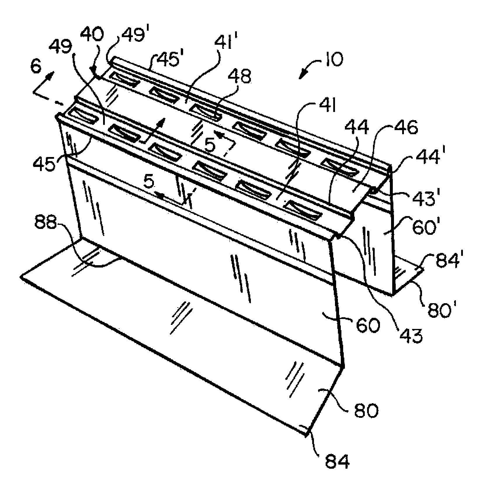
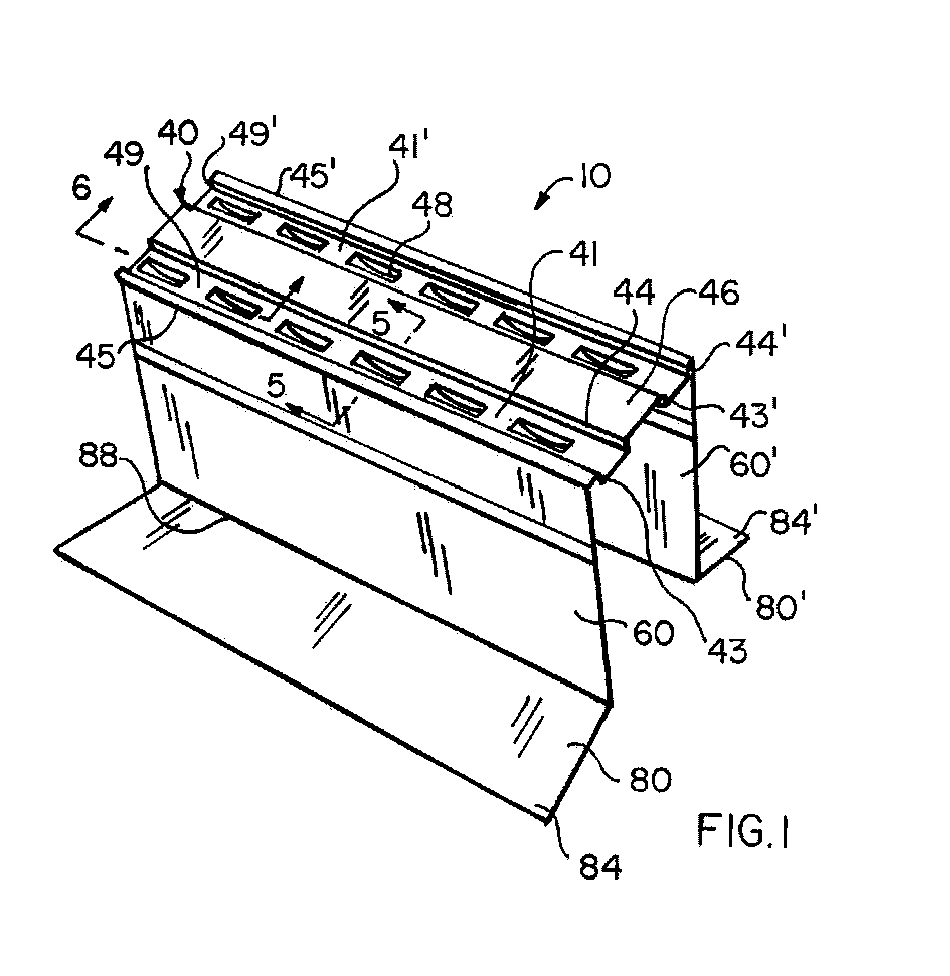
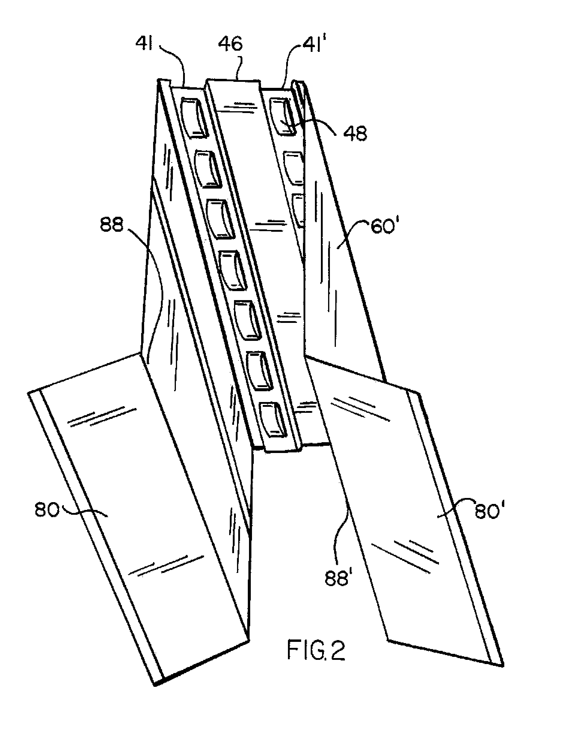
[0021]Referring now to the drawings, where the present invention is generally referred to with numeral 10, it can be observed that it basically includes an elongated cover 40, with longitudinal bends 45 and 45′ from where coextensive elongated spaced apart walls 60 and 60′ extend ending with longitudinally extending flange members 80 and 80′ at an angle that start from longitudinal bends 88 and 88′ that in turn terminate with flange folds 84 and 84′ defining flanges' distal folded ends 82 and 82′. The angle of flange members 80 and 80′ with respect to walls 60 and 60′ varies depending on the pitch of the roof structure to which the former are mounted.

[0022]Cover 40, in one of the embodiments, as shown in FIGS. 1, 2 and 3, includes two coextensive channels 41 and 41′ defined by lateral walls 43; 44; and 43′; 44′, respectively, separated by coextensive bottom walls 49 and 49′. Channels 41 and 41′ are separated from each other by longitudinal central spacer wall 46 and to the longitudi...


PUM


Abstract

A device for roof structures having a ridge or hip defined by the planes of two roof decks, disposed at an angle with respect to each other defining a longitudinal joint. A longitudinally extending cover with at least one coextensive channel defined by a bottom, two spacer walls and two lateral walls are mounted over the ridge or hip. The channel(s) increases the effective contact area to enhance the gripping action of the adhesive compound. From the longitudinal bends of the cover wall extend two perpendicularly extending walls with distal ends that continue with longitudinally coextensive flanges. The longitudinal flanges extend at an angle to be cooperatively and rigidly mounted over the roof decks with mechanical fasteners. An adhesive compound is positioned in the channel and over the cover. The adhesive is pressed so that part of it passes through and is lodged within the connected depressed slots positioned along the bottom, spacer and / or lateral walls that define the channel thereby creating a mechanical anchorage with the device. Tile accessories are placed over the cover and in contact with the adhesive compound to secure them to the device.

Description

OTHER RELATED APPLICATIONS[0001]The present application is a continuation-in-part of pending U.S. patent application Ser. No. 11 / 614,190, filed on Dec. 21, 2006, which is hereby incorporated by reference.BACKGROUND OF THE INVENTION[0002]1. Field of the Invention[0003]The present invention relates to roof hip and ridge anchor device, and more particularly, to such a device that is used in conjunction with an adhesive compound to secure the tiles to the device which in turn is mechanically anchored to the roof structure.[0004]2. Description of the Related Art[0005]Several designs for roof hip and ridge anchor devices have been designed in the past. None of them, however, include the anchorage features of the present invention while simultaneously keeping the design compatible with roll forming manufacturing processes. Roll forming techniques are suitable for relatively inexpensive production operations but carry inherent limitations. The present invention reconciles these limitations ...

Claims


Application Information

Patent Timeline
Patent Type & Authority Patents(United States)
IPC IPC(8): E04B7/00
CPCE04D12/008
Inventor CASTELLANOS, TOM
Owner EAST COAST METALS
Why Eureka
Try Eureka