Rechargeable battery

a rechargeable battery technology, applied in the field of rechargeable batteries, can solve the problems of reducing output performance, deteriorating durability, and degrading rigidity, and achieve the effects of increasing rigidity and durability, improving the bonding structure of the electrode terminal, and increasing output performan

Active Publication Date: 2011-05-26
SAMSUNG SDI CO LTD
View PDF2 Cites 17 Cited by
  • Summary
  • Abstract
  • Description
  • Claims
  • Application Information

AI Technical Summary

Benefits of technology

[0010]Embodiments of the present invention provide for a rechargeable battery with increased rigidity and durability by improving the bonding structure of an electrode terminal and an electrode uncoated region, and by increasing output performance by reducing the resistance between the electrode terminal and the electrode uncoated region.
[0011]Embodiments of the present invention provide for a rechargeable battery that avoids damaging the case by disconnecting a rough part of an electrode uncoated region from the case.
[0019]According to an embodiment, the cover and the terminal plate provide a recess portion through which the weld is formed to prevent the weld from protruding outside the cover and the terminal plate.
[0025]According to an embodiment of the present invention, the contact area between an electrode terminal and the current collector is maximized and the electrode terminal and the current collector are firmly fixed together. Therefore, resistance between the electrode terminal and the current collector is minimized to increase output performance, and damage to the bonded part of the electrode terminal and the current collector caused by external impact or vibration is effectively suppressed. In addition, long-term reliability and safety of the rechargeable battery are increased by avoiding problems of damage to the case.

Problems solved by technology

However, since the above-noted rechargeable battery has insufficient bonded area between the electrode terminal and the electrode uncoated region, and the thickness of the electrode uncoated region is much less, rigidity is degraded when the electrode terminal and the electrode uncoated region are bonded.
Therefore, the bonding parts may be easily broken by external impact or vibration to thereby deteriorate durability, and resistance between the electrode uncoated region and the electrode terminal is increased to thus reduce output performance.
Also, the electrode uncoated region may have rough parts, such as burrs formed in the process of manufacturing the electrode assembly, and the rough part of the electrode uncoated region in the rechargeable battery can directly contact the case to damage the case.
The damage to the case can substantially impact the reliability and safety of the rechargeable battery.

Method used


Image

  • Rechargeable battery
  • Rechargeable battery
  • Rechargeable battery

Examples


first embodiment

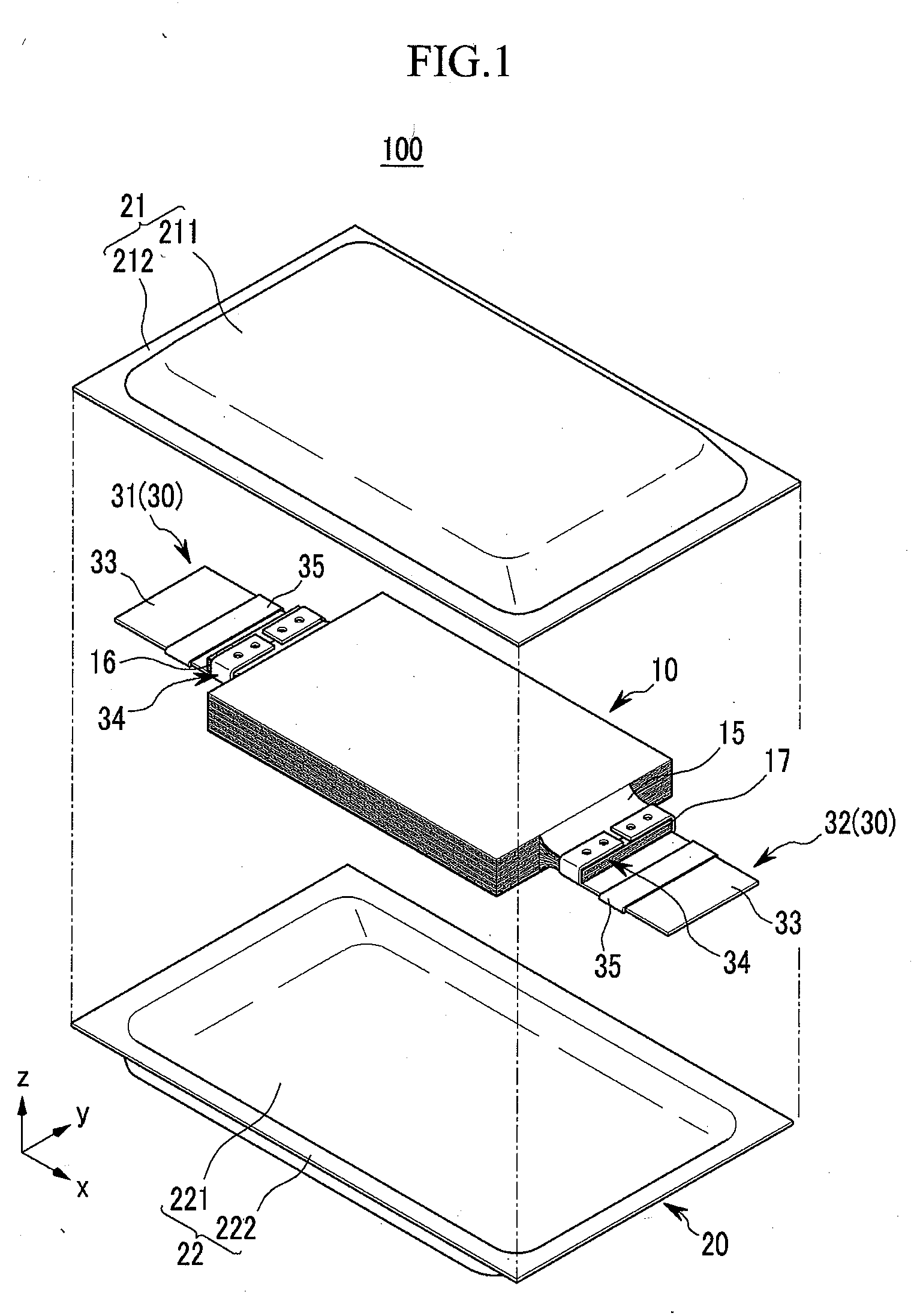
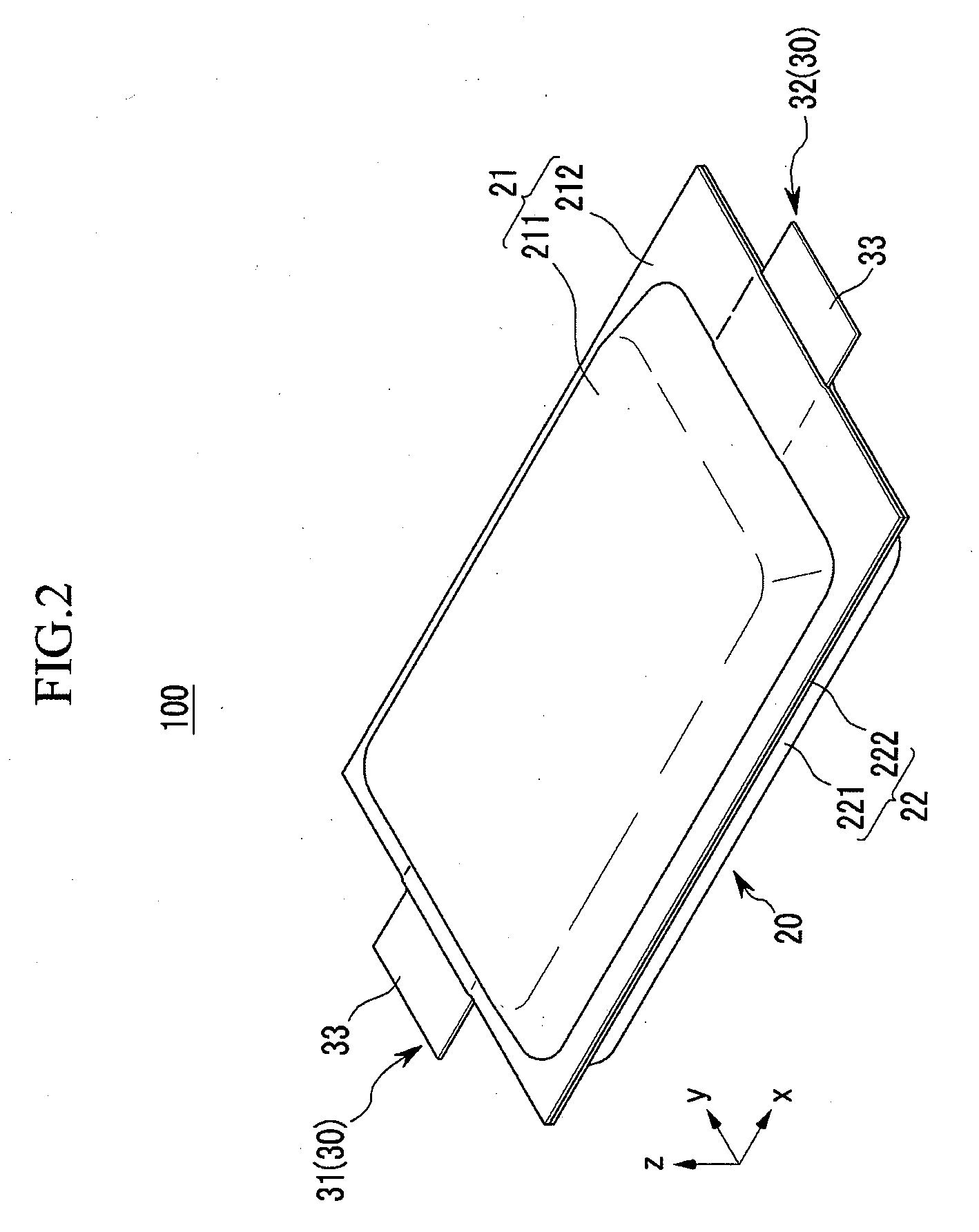
[0039]FIG. 1 shows an exploded perspective view of a rechargeable battery 100 according to the present invention, and FIG. 2 shows a combined state perspective view of a rechargeable battery shown in FIG. 1.

[0040]Referring to FIG. 1 and FIG. 2, the rechargeable battery 100 can include an electrode assembly 10, a case 20 for receiving the electrode assembly 10, and an electrode terminal 30 connected to the electrode assembly 10 and drawn outside the case 20. In this instance, the electrode terminal 30 may be formed to surround the top, bottom, and sides of an anode current collector 16 and a cathode current collector 17.

[0041]The electrode assembly 10 may have a stacked structure of a plurality sheets of anodes, separators, and cathodes, or it may have a structure in which a piece of an anode, a separator, and a cathode are stored and then rolled in a jelly roll form.

[0042]FIG. 3 shows a front view of an electrode assembly in a rechargeable battery shown in FIG. 1, exemplifying a lay...

second embodiment

[0064]FIG. 6 shows a partially magnified cross-sectional view of a rechargeable battery 200 according to the present invention.

[0065]Referring to FIG. 6, the rechargeable battery 200 according to the exemplary embodiment has the same configuration as the rechargeable battery according to the first embodiment, except for the use of a rivet 40 in combining the electrode terminal 30 and the current collectors 16 and 17, rather than a weld. The same members as those of the rechargeable battery according to first embodiment use the same reference numerals.

third embodiment

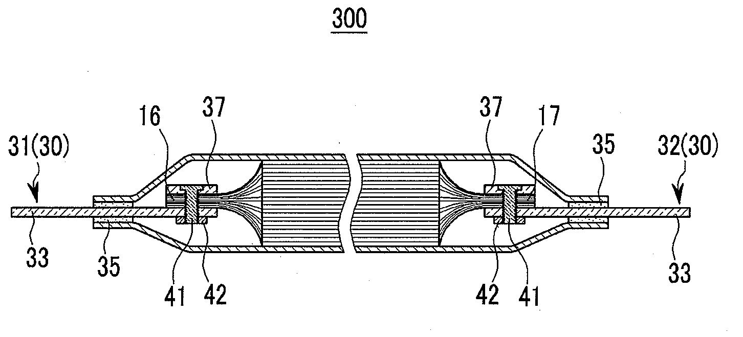
[0066]FIG. 7 shows a partially magnified cross-sectional view of a rechargeable battery 300 according to the present invention.

[0067]Referring to FIG. 7, the rechargeable battery 300 according to the third embodiment has the same configuration as that of the rechargeable battery according to the first exemplary embodiment, except for the use of a bolt 41 and nut 42 assembly in combining the electrode terminal 30 and the current collectors 16 and 17, rather than a weld. The same members as those of the rechargeable battery according to the first embodiment use the same reference numerals.

[0068]In the second embodiment and the third embodiment, conductive fastening members such as the rivet 40 or the bolt 41 may be used to fasten the electrode terminal 30 and the current collectors 16 and 17. In this case, an opening may be formed to be passed through the cover 37, the current collectors 16 and 17, and the terminal plate 33, and the conductive fastening member may be provided to be se...


PUM

PropertyMeasurementUnit
conductiveaaaaaaaaaa
heightaaaaaaaaaa
thicknessaaaaaaaaaa

Abstract

A rechargeable battery comprises an electrode assembly comprising an anode, a cathode, and a separator, a case for receiving the electrode assembly, and an electrode terminal electrically connected to the electrode assembly and drawn outside the case. The anode and the cathode each comprises an electrode uncoated region exposed past the separator and including a current collector at an edge. The electrode terminal comprises a terminal plate having a first terminal portion adhered to a bottom surface of the current collector and a second terminal portion drawn outside the case, and a combiner installed on the terminal plate to surround and adhere to a side surface and a top surface of the current collector.

Description

RELATED APPLICATIONS[0001]This application claims priority to and the benefit of Korean Patent Application No. 10-2009-0114166 filed in the Korean Intellectual Property Office on Nov. 24, 2009, the entire contents of which are incorporated herein by reference.BACKGROUND[0002]1. Field[0003]The present technology relates to a rechargeable battery. More particularly, embodiments of the present invention relate to a combined structure of an electrode uncoated region and an electrode terminal.[0004]2. Description of the Related Technology[0005]A rechargeable battery is typically rechargeable, in contrast to a primary battery that is not capable of being recharged. A low-capacity rechargeable battery is typically applicable to small portable electronic devices, such as mobile phones or laptop computers, and a medium to large capacity rechargeable battery is typically used to drive a motor or store power for cases of an electric vehicle and a hybrid vehicle.[0006]The rechargeable battery t...

Claims


Application Information

Patent Timeline
Patent Type & Authority Applications(United States)
IPC IPC(8): H01M2/06H01M50/54H01M50/548H01M50/557H01M50/566
CPCH01M10/0436H01M2/1011H01M2/0212H01M2/266H01M10/5051H01M10/6553Y02E60/10H01M50/557H01M50/54Y02P70/50H01M50/548H01M50/566H01M10/0413H01M10/0431H01M50/538H01M50/124H01M50/10H01M50/116H01M50/183H01M50/256
Inventor KIM, JUN-SIKYANG, JAE-MINHWANG, JAE-HYUNKIM, SUNG-SOO
Owner SAMSUNG SDI CO LTD
Why Eureka
Try Eureka