
Bicycle control device

a control device and bicycle technology, applied in the direction of cycle brakes, cycle equipment, braking systems, etc., can solve the problems of not allowing the piston to operate efficiently, and achieve the effect of facilitating the depressing of the rod par

Active Publication Date: 2017-08-01
SHIMANO INC
View PDF37 Cites 1 Cited by
  • Summary
  • Abstract
  • Description
  • Claims
  • Application Information

AI Technical Summary

Benefits of technology

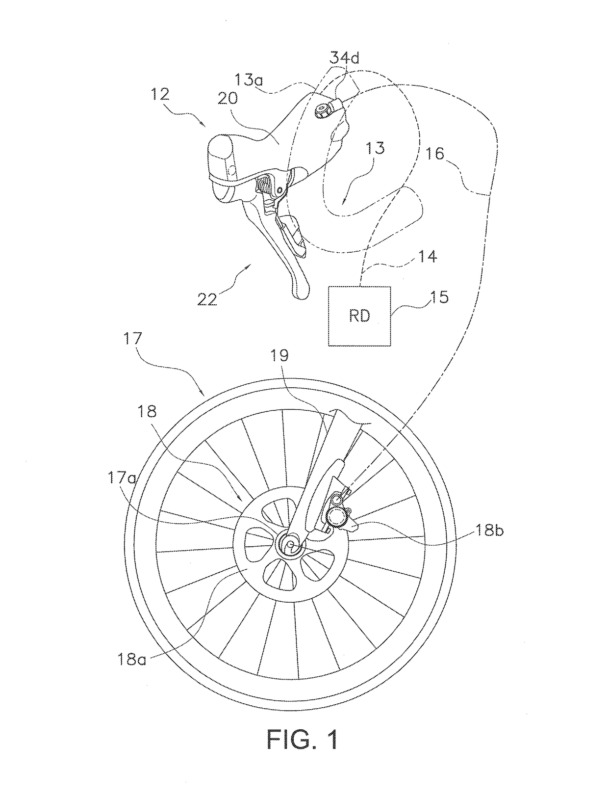
[0008]One object of the present invention is to provide a bicycle control device having a shift-operating mechanism in a grip part and capable of performing a shifting operation and a braking operation, wherein the piston can be operated efficiently relative to the pivoting of the control lever member when the hydraulic pressure-generator part is provided inside the grip part.
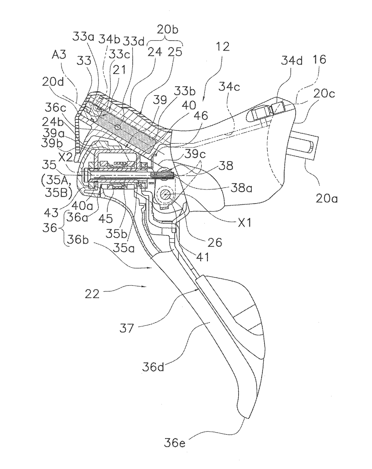
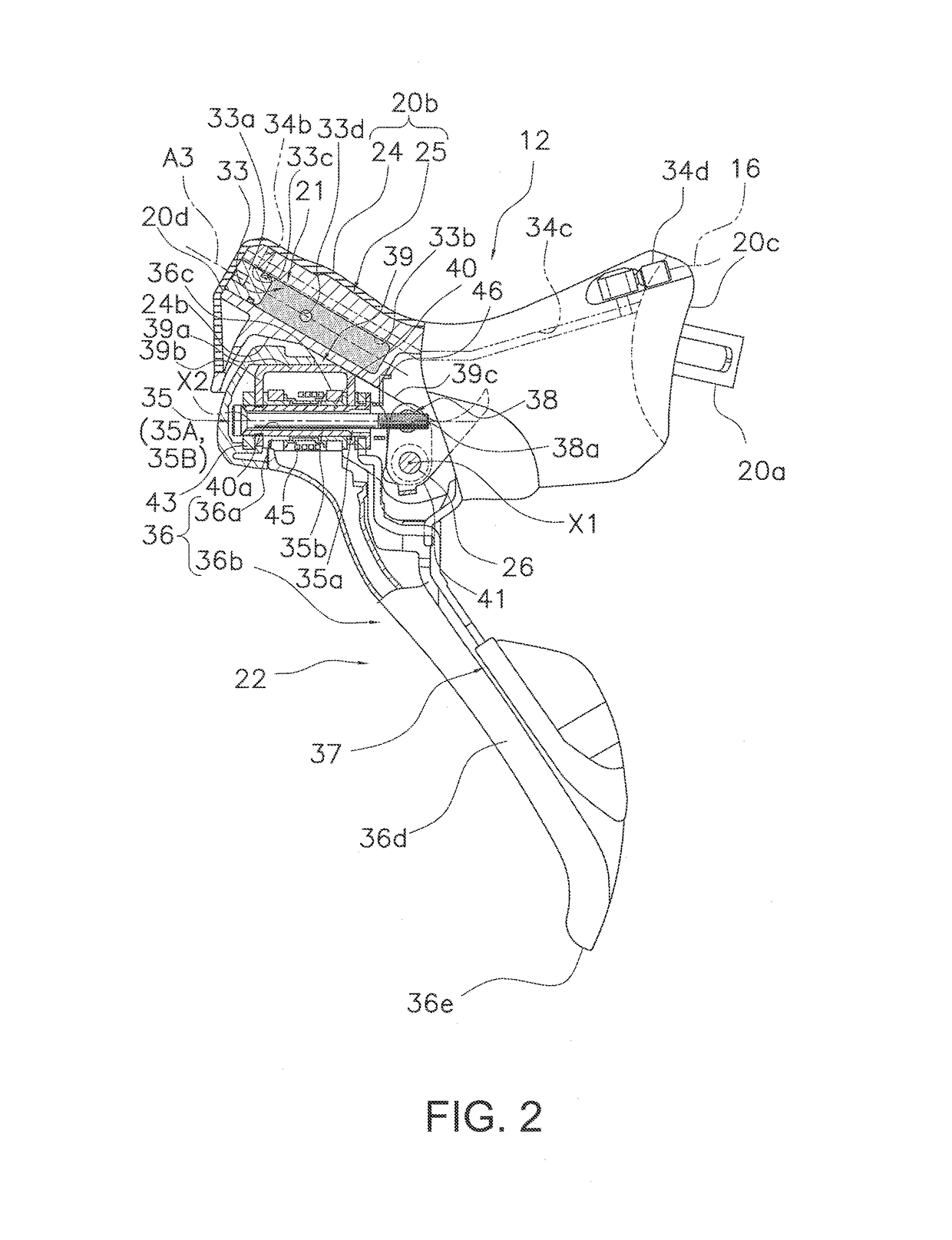
[0010]In this bicycle control device, the shifting device is operated via the control cable by holding the grip part of the housing member and operating a first operating lever to actuate the shift-operating mechanism. Also, the braking device is controlled by a hydraulic pressure generated when the cam member actuates the rod part by operating the first operating lever around the first axis, and the piston is moved. In this arrangement, the rod part of the hydraulic pressure-generating part is actuated by the cam member. Therefore, the piston can be actuated efficiently relative to the pivoting of the control lever member even when the hydraulic pressure-generating part is provided inside the grip part. Furthermore, the speed of movement of the rod part relative to the pivoting of the control lever member can be adjusted by appropriately forming the cam surface of the cam member.
[0012]In accordance with a third aspect, the bicycle control device according to the second aspect is configured so that the first end of the rod part is coupled to the piston to pivot around an axis parallel to the first axis. In this aspect, by the rod part pivots around the axis parallel to the first axis, this makes it easier for the rod part to be depressed by the cam member.
[0013]In accordance with a fourth aspect, the bicycle control device according to the second or third aspect is configured so further comprises a roller provided on the second end of the rod part to rotate relative to the rod part. In this aspect, the roller part is provided to the second end in contact with the cam member for allowing the roller to rotate when depressed by the cam member. Therefore, the rod part can be depressed smoothly by the cam member.
[0015]In accordance with a sixth aspect, the bicycle control device according to any of the first to fifth aspects is configured so that the hydraulic pressure-generator is provided on the second end of the grip part, and has a guide groove for guiding the second end of the rod part closer to the cylinder center axis upon the rod part being depressed by the cam member. In this aspect, the rod part is moved closer to the cylinder center axis by the guide groove due to the braking operation of the first operating lever around the first axis, allowing the moving speed of the piston inside the cylinder to increase gradually in accordance with the pivot amount of the first operating lever. Therefore, the braking operation can be performed quickly.
[0017]According to the present invention, the rod part of a hydraulic fluid pressure generator is actuated by a cam member, allowing the piston to be efficiently actuated relative to the pivoting of a control lever member even when the hydraulic fluid pressure generator is provided inside a grip part.

Problems solved by technology

In this way, once the control lever member is coupled to the rod part by a link when the placement of the hydraulic pressure-generating part is limited, there is danger that, the placement of the cylinder and control lever member will not allow the piston to operate efficiently relative to the pivoting of the control lever member.

Method used


Image

  • Bicycle control device
  • Bicycle control device
  • Bicycle control device

Examples


first modification

[0083]In the following description, only those features differing from the embodiment described above are described and numbered in the drawings, and description of the configuration and operation of other features similar to those of the embodiment described above, as well as numbering thereof in the drawings, will be omitted.

[0084]In the embodiment described above, the second axis X2 and the cable take-up axis A2 were coaxial, but the present invention is not limited to such a configuration. As shown in FIG. 11, the second axis X2 and the cable take-up axis A2 can be on different axes in a control device 112. In FIG. 11, the cable take-up axis A2 of a shift-operating mechanism 123 is disposed below the second axis X2 of a control lever member 122. The cable take-up axis A2 and the second axis X2 may also be disposed so as to intersect.

second modification

[0085]In the embodiment described above, the adjustment bolt 35b of the adjustment mechanism 35 (i.e., the piston-position-adjusting mechanism 35A and the control lever position adjustment mechanism 35B) is disposed penetrating the support shaft 40 along the second axis X2, but the present invention is not limited to such a configuration. In a control device 212 according to a second modification, as shown in FIGS. 12A and 12B, an adjustment bolt 235b (an example of a second adjustment bolt, a fourth adjustment bolt, or a sixth adjustment bolt) serving as an adjustment member 235a (an example of a second adjustment member or a fourth adjustment member) of an adjustment mechanism 235 (constituted by a piston-position-adjusting mechanism 235A and a control lever position adjustment mechanism 235B) is disposed near a lever shaft 26 having a first axis X1. The adjustment bolt 235b is screwed into a screw hole 236g formed in the lever 36b, and an end thereof contacts a coupling part 241b...

third modification

[0086]In a control device 312 according to a third modification, as shown in FIGS. 13A and 13B, an adjustment member 335a (an example of a first adjustment member) of an adjustment mechanism 335 (constituted by a piston-position-adjusting mechanism 335A and a control lever position adjustment mechanism 3359) is constituted by a worm gear bolt 335b attached to a cam member 341. The worm gear bolt 335b has worm gear cogs 335c formed on an outer circumferential surface. Worm wheel cogs 339d meshing with the worm gear cogs 335c are formed on one of a pair of side plates 339c of a first bracket 339 of a support member 336a. In this case, the adjustment bolt of the embodiment described above is used as a coupling bolt for coupling a second bracket 339 of the control lever member 22 and a cam member 341.


PUM


Abstract

A bicycle control device includes a housing member, a shift-operating mechanism, a hydraulic fluid pressure generator and a control lever member. The housing member has an attachment part for attachment to a handlebar, and a grip part extending longitudinally between first and second ends of the grip part. The shift-operating mechanism is coupled to a shifting device by a control cable. The hydraulic fluid pressure generator has a cylinder, a piston movably disposed within the cylinder to generate fluid pressure for controlling a braking device, and a rod part coupled to the piston. The control lever member has a cam member arranged to actuate the rod part, and a first operating lever coupled to the cam member. The first operating lever is pivotal around a first axis relative to the housing member and actuates the cam member by pivoting around the first axis.

Description

CROSS-REFERENCE TO RELATED APPLICATIONS[0001]This application claims priority under 35 U.S.C. §119 to Japanese Patent Application No. 2012-007808, filed Dec. 26, 2012. The entire disclosure of Japanese Patent Application No. 2012-007808 is hereby incorporated herein by reference.BACKGROUND[0002]Field of the Invention[0003]This invention generally relates to a bicycle control device. More specifically, the present invention relates to a bicycle control device which can be mounted on the handlebar of a bicycle and which can control a braking device and a shifting device.[0004]Background Information[0005]Bicycle control devices are conventionally known, which can be mounted on a handlebar of a bicycle for controlling both a braking device and a shifting device (for example, see European Patent Application Publication No. 2308750). This prior art bicycle control device is provided with a housing member having an attachment part capable of being attached to a handlebar and a grip part ca...

Claims


Application Information

Patent Timeline
Patent Type & Authority Patents(United States)
IPC IPC(8): B62M25/04B60T7/10B60T11/16B60T11/18B62L3/02B62K23/06
CPCB62M25/04B60T7/102B60T11/16B60T11/18B62K23/06B62L3/023Y10T74/20024
Inventor WATARAI, ETSUYOSHIKARIYAMA, OSAMUMATSUSHITA, TATSUYANAKAKURA, MASAHIRO
Owner SHIMANO INC
Learn More