Apparatus and method for protecting overvoltage of high voltage inverter

Active Publication Date: 2011-06-30
LS IND SYETEMS CO LTD
View PDF7 Cites 1 Cited by
  • Summary
  • Abstract
  • Description
  • Claims
  • Application Information

AI Technical Summary

Benefits of technology

[0015]Therefore, an overvoltage protection apparatus of a high voltage inverter according to one embodiment of the present invention comprises a sawtooth wave generation unit generating a sawtooth wave having a predetermined frequency and a voltage level, an analog reference voltage generation unit converting a voltage command signal inputted from a main control unit to an analog reference voltage, a comparison unit comparing the voltage levels of the sawtooth wave and the analog reference voltage to generate a PWM (Pulse Width Modulation) signal, a pulse width determination unit determining the pulse width of the PWM signal; and a PWM signal output unit adjusting the pulse width of the PWM signal according to the determination of the pulse width determination unit.
[0016]According to an aspect of one embodiment of the present invention, the PWM signal output unit outputs the PWM signal as it is, in a case the pulse width o

Problems solved by technology

Hence, a voltage reflection phenomenon takes place where a voltage produced at the inverter and supplied through the cable to the electric motor reflects at a discontinuity point of the impedance, resultantly creating voltage fluctuations.
However, overlap of the produced voltage fluctuations causes an over-voltage more than a pressure resistant to the load insulation applies to a load to thereby produce insulation breakage and bearing damage, etc. due to the stress accumulation in a load.
However, the use of a high voltage inverter of cascade H-bridge mode fails to completely remove voltage fluctuations, and there still occurs voltage fluctuations causing damage to a load.

Method used


Image

  • Apparatus and method for protecting overvoltage of high voltage inverter
  • Apparatus and method for protecting overvoltage of high voltage inverter
  • Apparatus and method for protecting overvoltage of high voltage inverter

Examples


Embodiment Construction

[0022]The following detailed description is by method of example, and it merely shows an embodiment of the invention. In addition, the principle and concept of the present invention will be provided for the most useful and easy description.

[0023]Thus, detailed structures unnecessarily required in the basic understanding of the present invention have not been provided, and several kinds of forms possibly practiced by one skilled in the art from the substance of the invention will be exemplified through the drawings.

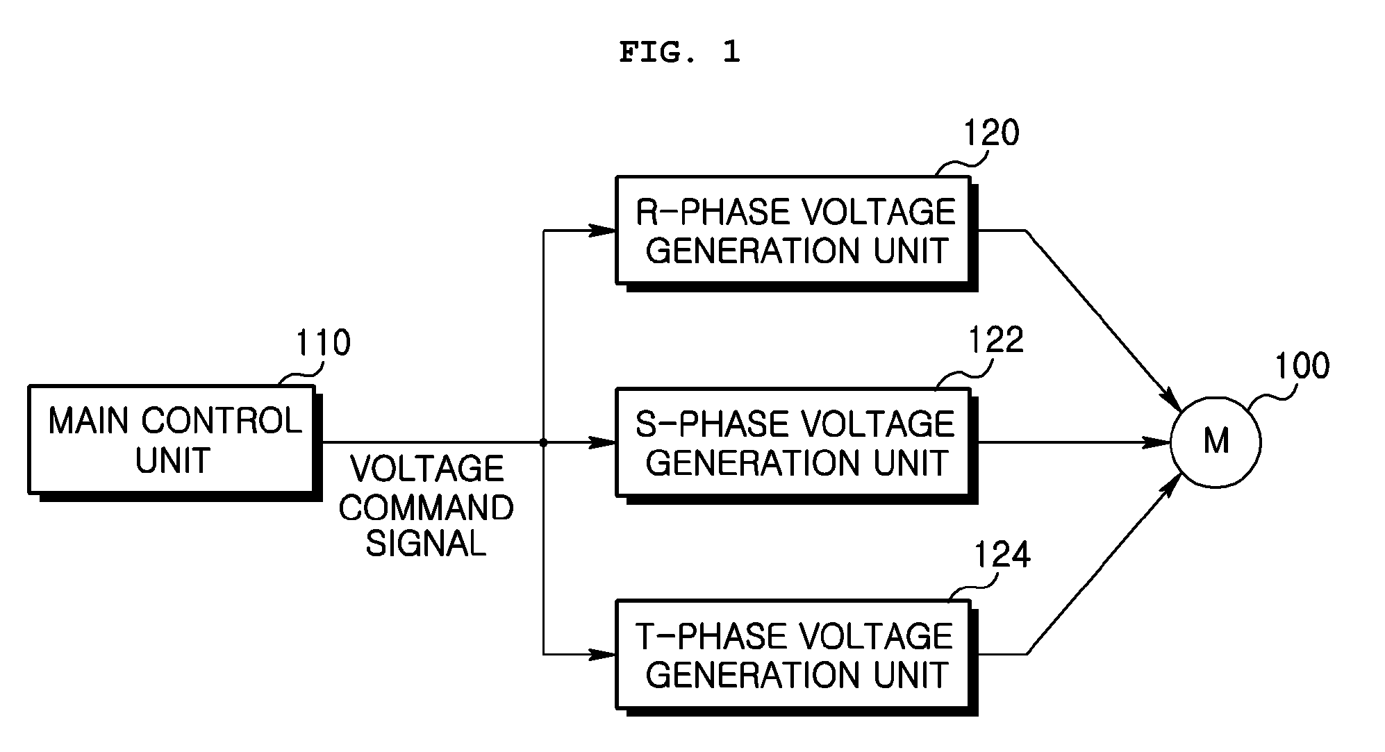
[0024]FIG. 1 is diagram showing the construction of a high voltage inverter. Herein, a symbol 100 indicates a load. For example, the load is a 3-phase alternating electric motor driven by a 3-phase alternating voltage.

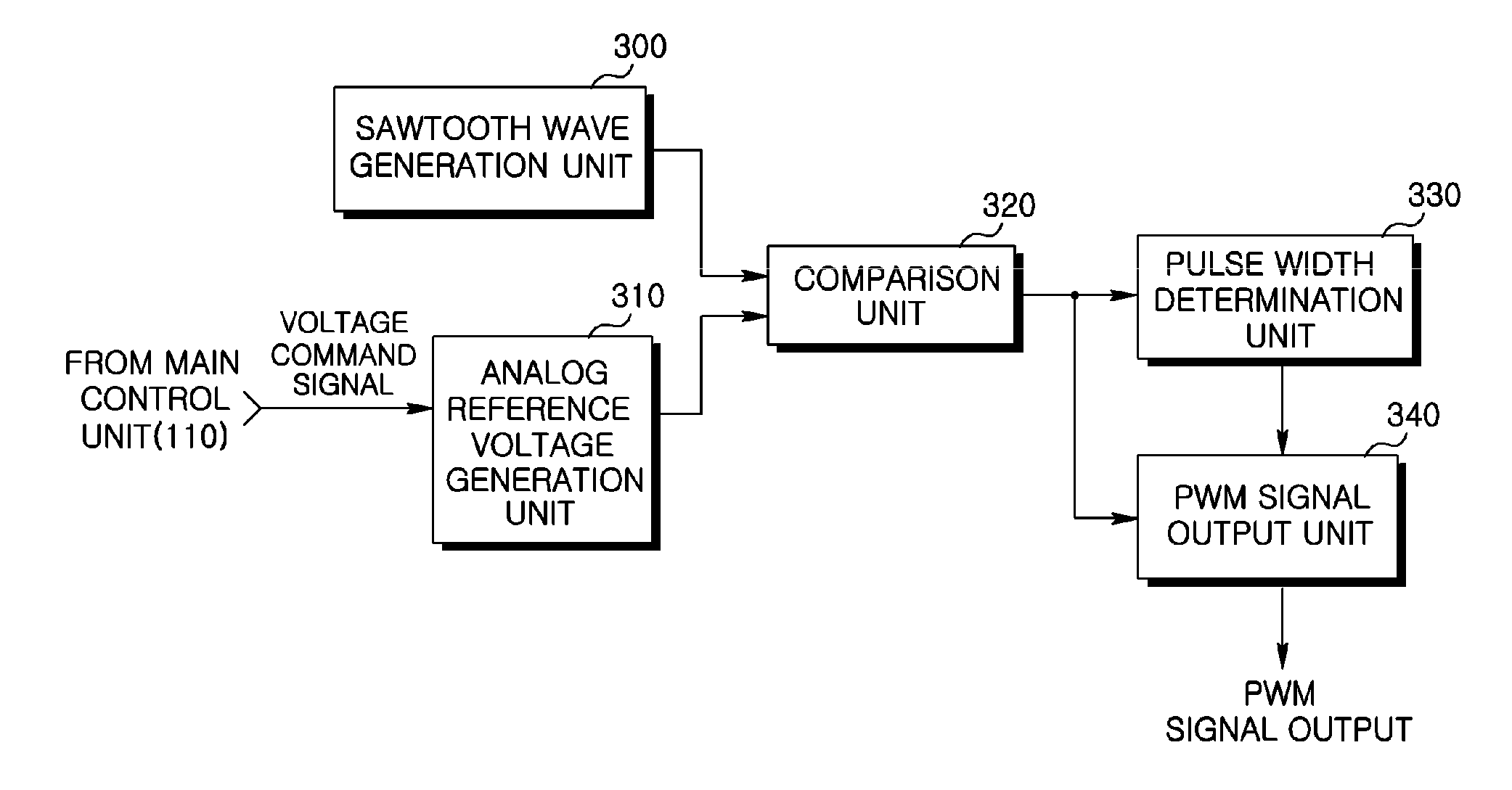
[0025]A symbol 110 indicates a main control unit. The main control unit 110 determines the drive status of the load 100, and generates a voltage command signal including a reference voltage for generating a PWM signal according to the determined drive status....


PUM


Abstract

Disclosed herein is an overvoltage protection apparatus and method of a high voltage inverter adapted to protect a load without any adverse effect from an overvoltage aroused by voltage fluctuation attributable to an impedance difference among an inverter, a load and a cable connected between the inverter and the load, wherein the apparatus and method converts a voltage command signal given as a digital signal into an analog reference signal by a main control unit, compares the analog reference voltage with a sawtooth wave having a predetermined voltage level and frequency in order to generate a PWM (Pulse Width Modulation) signal, determines the pulse width of the PWM signal, and converts the pulse width of the PWM signal to have a predetermined time interval in a case the pulse width of the PWM signal is less than a predetermined time interval.

Description

CROSS-REFERENCE TO RELATED APPLICATIONS[0001]Pursuant to 35 U.S.C. §119(a), this application claims the benefit of earlier filing date and right of priority to Korean Application No. 10-2009-0134688, filed on Dec. 30, 2009, the contents of which are hereby incorporated by reference herein in their entirety.BACKGROUND OF THE INVENTION[0002]1. Field of the Invention[0003]The present invention relates to an overvoltage protection apparatus and method of a high voltage inverter. More especially, the present invention relates to an overvoltage protection apparatus and method of a high voltage inverter adapted to protect a load without any adverse effect from an overvoltage aroused by voltage fluctuation attributable to an impedance difference among an inverter, a load and a cable connected between the inverter and the load.[0004]2. Description of the Related Art[0005]In general, inverters are much used in the case of accurately driving a load such as 3-phase electric motors. In order to ...

Claims


Application Information

Patent Timeline
IPC IPC(8): H02H9/04H02M7/48
CPCH02P29/022H02P29/032H02M7/4835H02M1/32
Inventor KIM, HYO JIN
Owner LS IND SYETEMS CO LTD
Why Eureka
Try Eureka