
Developing device and image forming apparatus including the same

a technology of developing device and image forming apparatus, which is applied in the direction of electrographic process apparatus, instruments, optics, etc., can solve the problems of increasing manufacturing costs, deterioration of developer, and reducing the mixing and agitation performance of developer, and achieves the effect of being inexpensive and small

Active Publication Date: 2011-06-30
HEWLETT PACKARD DEV CO LP
View PDF8 Cites 18 Cited by
  • Summary
  • Abstract
  • Description
  • Claims
  • Application Information

AI Technical Summary

Benefits of technology

[0014]The present general inventive concept provides a developing device that is inexpensive and small by including an agitating and conveying member having both an agitation function and a conveying function, and an image forming apparatus including the developing device.

Problems solved by technology

However, as developing units have become smaller in recent years, the developer mixing and agitating performance has decreased.
However, if the number of augers is increased in order to lengthen the mixing and agitation path, the number of parts, such as a housing for storing the augers, a bearing for the augers, and a sealing member, is increased, thereby increasing manufacturing costs.
Also, since excessive stress is applied to the developer in the previous agitation chamber, the developer deteriorates.
However, although the developer agitating performance at an early stage is good, if the protruding agitating member is used for a long time, fiber-like foreign materials may be wound around the protruding agitating member, thereby degrading the developer agitating performance.
Also, when the protruding agitating member, which is easily deformed, is used, the protruding agitating member may be deformed, thereby easily coagulating the developer.
Also, in this case, since an excessive amount of developer remains, a large space for the remaining developer is needed, thereby increasing the size of a device.

Method used


Image

  • Developing device and image forming apparatus including the same
  • Developing device and image forming apparatus including the same
  • Developing device and image forming apparatus including the same

Examples


Embodiment Construction

[0031]Reference will now be made in detail to the embodiments of the present general inventive concept, examples of which are illustrated in the accompanying drawings, wherein like reference numerals refer to the like elements throughout. The embodiments are described below in order to explain the present general inventive concept by referring to the figures.

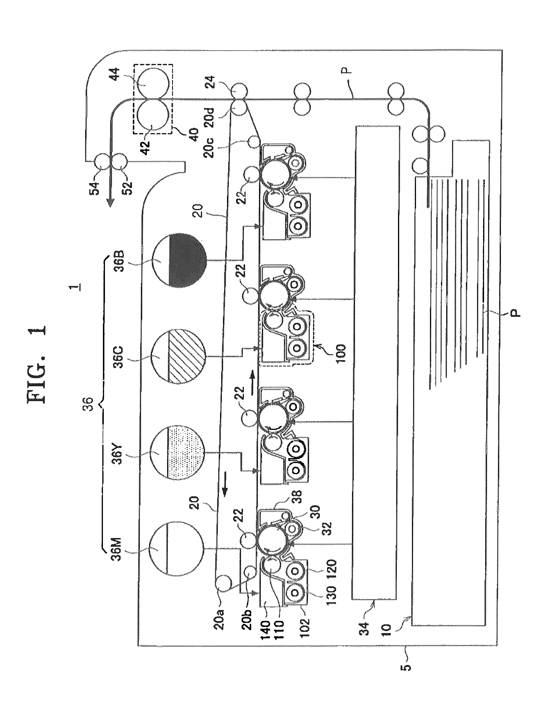
[0032]FIG. 1 is a cross-sectional view illustrating an image forming apparatus 1 according to an embodiment of the present general inventive concept.

[0033]Referring to FIG. 1, the image forming apparatus 1 includes a recording medium conveying unit 10, a transfer unit including a transfer belt 20 as an intermediate transfer body, a photosensitive drum 30 to hold an electrostatic latent image, a developing unit 100 to develop the electrostatic latent image formed on the photosensitive drum 30, and a fixing unit 40. The developing unit 100 may be applied to a tandem-type image forming apparatus.

[0034]The recording medium conveying...


PUM


Abstract

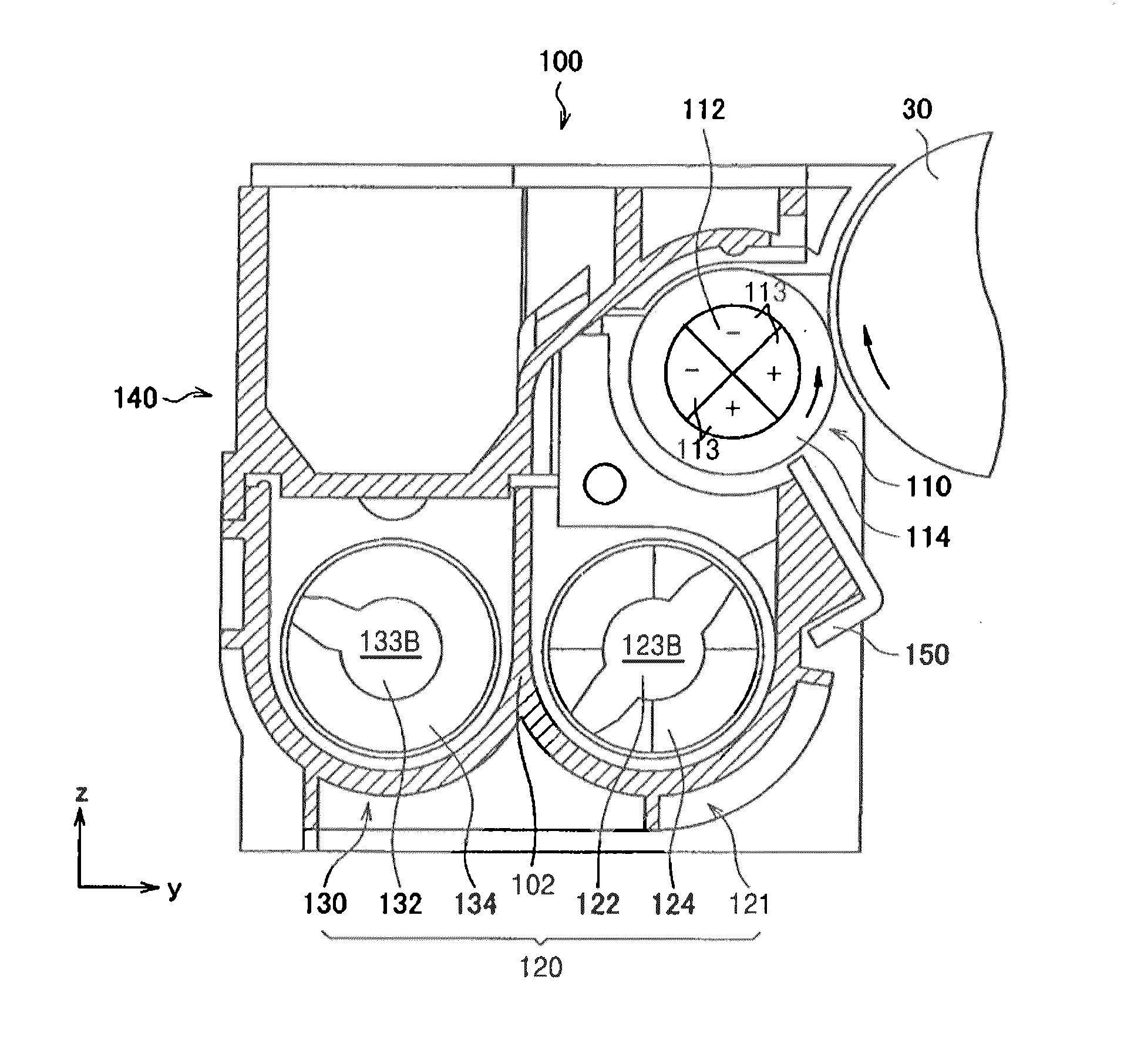
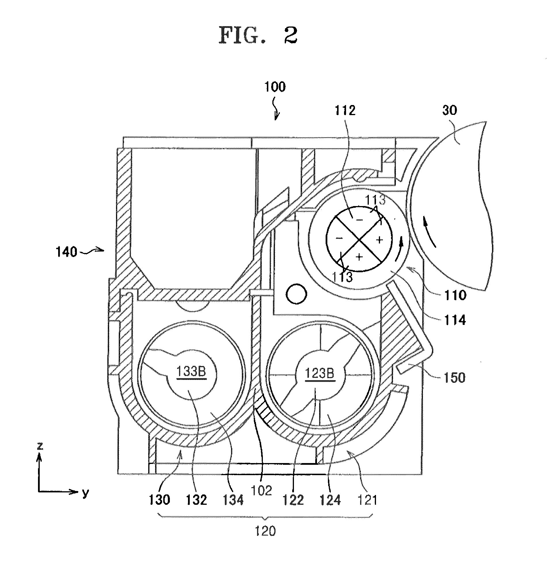
A developing device and an image forming apparatus including the same includes an agitating and conveying unit that receives a developer, and at least one agitating and conveying member to mix and agitate the developer and convey the developer in a developer conveying direction. A developing roller faces a photosensitive drum on which an electrostatic latent image is formed, and attaches the developer to an outer surface of the developing roller. The agitating and conveying member includes a support shaft extending in the developer conveying direction. A plurality of agitation wings disposed on an outer surface of the support shaft to mix and agitate the developer. At least one paddle protrudes from the support shaft in a radial direction and extends along the shaft between adjacent agitation wings. The at least one paddle has a height increasing from an upstream side to a downstream side of the developer conveying direction.

Description

CROSS-REFERENCE TO RELATED APPLICATIONS[0001]This application claims priority under 35 U.S.C. §119(a) from Japanese Patent Application No. 2009-295945, filed on Dec. 25, 2009, in the Japanese Patent Office, and also Korean Patent Application No. 10-2010-0069606, filed on Jul. 19, 2010, in the Korean Intellectual Property Office, the disclosures of which are incorporated herein in their entirety by reference.BACKGROUND[0002]1. Field of the Invention[0003]The present general inventive concept relates to a developing device and an image forming apparatus using a two-component developing method.[0004]2. Description of the Related Art[0005]In general, an auger, which is a shaft with a spiral wing, is used as a developer agitating and conveying member. However, as developing units have become smaller in recent years, the developer mixing and agitating performance has decreased. In order to solve this problem, the developer mixing and agitating performance is maintained in relation to the ...

Claims


Application Information

Patent Timeline
IPC IPC(8): G03G15/08
CPCG03G2215/0827G03G15/0877G03G15/0893G03G15/0889G03G15/08
Inventor IWATA, NAOYA
Owner HEWLETT PACKARD DEV CO LP
Learn More