Radial channel diffuser for steam turbine exhaust hood

a diffuser and steam turbine technology, applied in the direction of machines/engines, stators, liquid fuel engines, etc., can solve the problems of destroying the ability of the diffuser to raise the static pressure, operating with significantly less effectiveness at other flows, and unable to design fully effective diffusers, etc., to achieve the effect of reducing vortex flow, improving flow patterns and diffusion performan

Inactive Publication Date: 2011-06-30
GENERAL ELECTRIC CO
View PDF8 Cites 11 Cited by
  • Summary
  • Abstract
  • Description
  • Claims
  • Application Information

AI Technical Summary

Benefits of technology

[0011]Accordingly, it would be desirable to eliminate vortex flow in the upper exhaust hood and provide improved flow patterns and diffusion performance, particularly in the upper exhaust hood.

Problems solved by technology

However, while such vanes may be optimized for one set of flow conditions, they may operate with significantly less effectiveness at other flows.
Unfortunately, the complicated flow patterns existing in such turbines as well as the design problems caused by space limitations make fully effective diffusers almost impossible to design.
A frequent result is flow separation that fully or partially destroys the ability of the diffuser to raise the static pressure as the steam velocity is reduced by increasing the flow area.
With the use of an exhaust hood supporting the turbine, bearings and ancillary parts, the exhaust steam path is tortuous and subject to pressure losses with consequent reduction in performance and efficiency.
This results in strong vortex formation 38 behind the steam guide 24 in upper exhaust hood and minimizes the effective flow area between the steam guide and outer wall of the hood, thereby increasing losses in the steam path as well.
This phenomena decreases the flow diffusion in upper half of exhaust hood, results in degradation of exhaust hood performance, which has direct impact on the last stage bucket performance.

Method used


Image

  • Radial channel diffuser for steam turbine exhaust hood
  • Radial channel diffuser for steam turbine exhaust hood
  • Radial channel diffuser for steam turbine exhaust hood

Examples


first embodiment

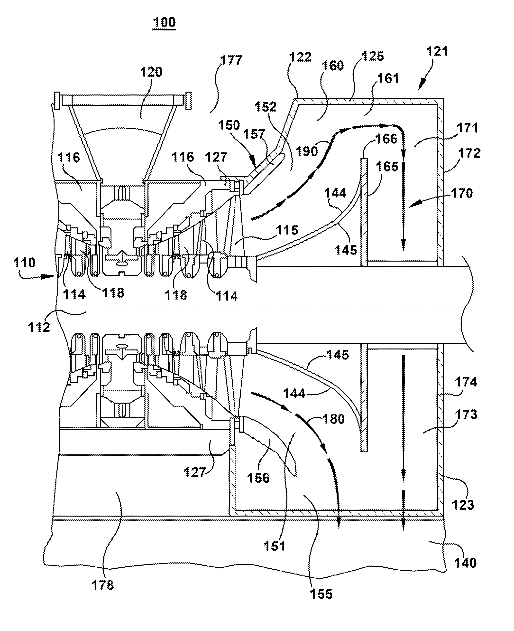
[0028]the present invention provides an exhaust arrangement 121 for an axial flow steam turbine as illustrated in FIG. 3. An inner turbine casing 116 includes one or more turbine stages of nozzles 114 and buckets 118 providing an axial steam flow path through the inner turbine casing 116. An exhaust outlet flows from multiple last stage buckets 115. An exhaust hood 125 is coupled to a downstream axial end 127 of the inner turbine casing 116. A turbine condenser 140 is mounted below the exhaust hood 125 for condensing and subcooling the exhausted steam. For a dual axial steam turbine, an exhaust hood 125 is coupled at each downstream axial end 127 of the inner casing 116 with one or more turbine condensers 140 accepting the exhausted steam.

[0029]The exhaust hood 125 provides a dual exhaust path from the last stage buckets 118 to the turbine condenser 140. The exhaust hood 125 may include an upper exhaust hood 122 and a lower exhaust hood 123 separated conventionally along a horizonta...

second embodiment

[0035]The radial channel may be formed with different shape and contouring of outer casing as shown in FIGS. 5-6. In the present invention, the configuration of the radial channel is modified. The two descending exhaust spaces of the radial channel in fluid communication with the upper section of the radial channel and with the turbine condenser may include an exhaust space on each lateral side of the exhaust hood. The descending exhaust space on each respective lateral side may extend radially outboard relative to the exhaust hood in a path to the turbine condenser below. The descending exhaust space may further curve upstream axially such that it descends vertically alongside the outer radial casing of the exhaust hood in a vertical path to the turbine condenser below. Alternatively the vertically descending exhaust space may be enclosed in a separately enclosed volume that exhausts downward to the turbine condenser in a parallel path relative to the condenser flow from the lower ...


PUM


Abstract

An exhaust hood for an axial steam turbine that includes a radial channel, downstream from the normal flow pattern. The radial channel guides the exhaust steam flow in upper half of the hood in the flow momentum direction. Due to this pattern of flow direction, vortex generation in upper exhaust hood is reduced and increased flow diffusion results. The geometric arrangement can eliminate the outer casing of the exhaust hood over the axial length of the turbine inner casing, allowing the turbine inner casing to be supported directly by a foundation for the steam turbine.

Description

BACKGROUND OF THE INVENTION[0001]The invention relates generally to steam turbines and more specifically to exhaust hoods for efficiently diffusing steam to a condenser.[0002]In the discharge of exhaust steam from an axial flow turbine, for example discharge of this exhaust steam to a condenser, it is desirable to provide as smooth a flow of steam as possible and to minimize energy losses from accumulation of vortices, turbulences and non-uniformity in such flow. Usually the exhaust from the turbine is directed into an exhaust hood and from there through a discharge opening in the hood in a direction essentially normal to the axis of the turbine into a condenser. It is desirable to achieve a smooth transition from axial flow at the exhaust of the turbine to radial flow in the exhaust hood and thence a smooth flow at the discharge opening of this hood into the condenser.[0003]In the constructing of an effective exhaust hood for use with such an axial flow turbine it is desirable to a...

Claims


Application Information

Patent Timeline
Patent Type & Authority Applications(United States)
IPC IPC(8): F01D25/24
CPCF01D25/30
Inventor DALSANIA, PRAKASH B.JOHN, JOSHY
Owner GENERAL ELECTRIC CO
Why Eureka
Try Eureka