Vehicle speed control device

Active Publication Date: 2011-06-30
ADVICS CO LTD
View PDF3 Cites 17 Cited by
  • Summary
  • Abstract
  • Description
  • Claims
  • Application Information

AI Technical Summary

Benefits of technology

[0010]The present invention has been made on the basis of the above discovery and knowledge, and it is an aspect of the present invention to provide a speed control device of an in-wheel motor vehicle which is capable of suppressing the occurrence of an unnecessary front-rear skid of left and right wheels in a vehicle turning state by appropriately controlling the electric motors of the left and right wheels.
[0029](When the actual speed of the vehicle is equal to or lower than the predetermined value (vz1) and) when the steering angle is greater than a predetermined value, the turning center may be determined at a point positioned closer side to the vehicle with respect to a reference line which is in parallel to the front-rear direction of the vehicle and passes a point placed on the extension line of the rear wheel axle of the vehicle and distant from the standard position of the rear wheel axle inwardly in the turning direction by a turning radius obtained by dividing the wheel base of the vehicle by the tangent of the steering angle. According to this configuration, in particular, in the very low-speed zone where centrifugal force is negligible, when the steering angle is greater, the turning center comes closer to the vehicle, so that the turning radius is reduced. As a result, “small-radius turning ability” is improved. The small-radius turning ability refers to ease of reducing the turning radius.

Problems solved by technology

However, in practice, it is very difficult to design a steering device in which the steering angles of the left and right steering wheels are adjusted in faithful accordance with the theoretical characteristics of the Ackermann geometry.
In the in-wheel motor vehicle, if the electric motors of the left and right wheels are not appropriately controlled in the vehicle turning state, an unnecessary front-rear skid may occur in the left and right wheels due to the difference in the movement locus between the left and right wheels.

Method used


Image

  • Vehicle speed control device
  • Vehicle speed control device
  • Vehicle speed control device

Examples


Embodiment Construction

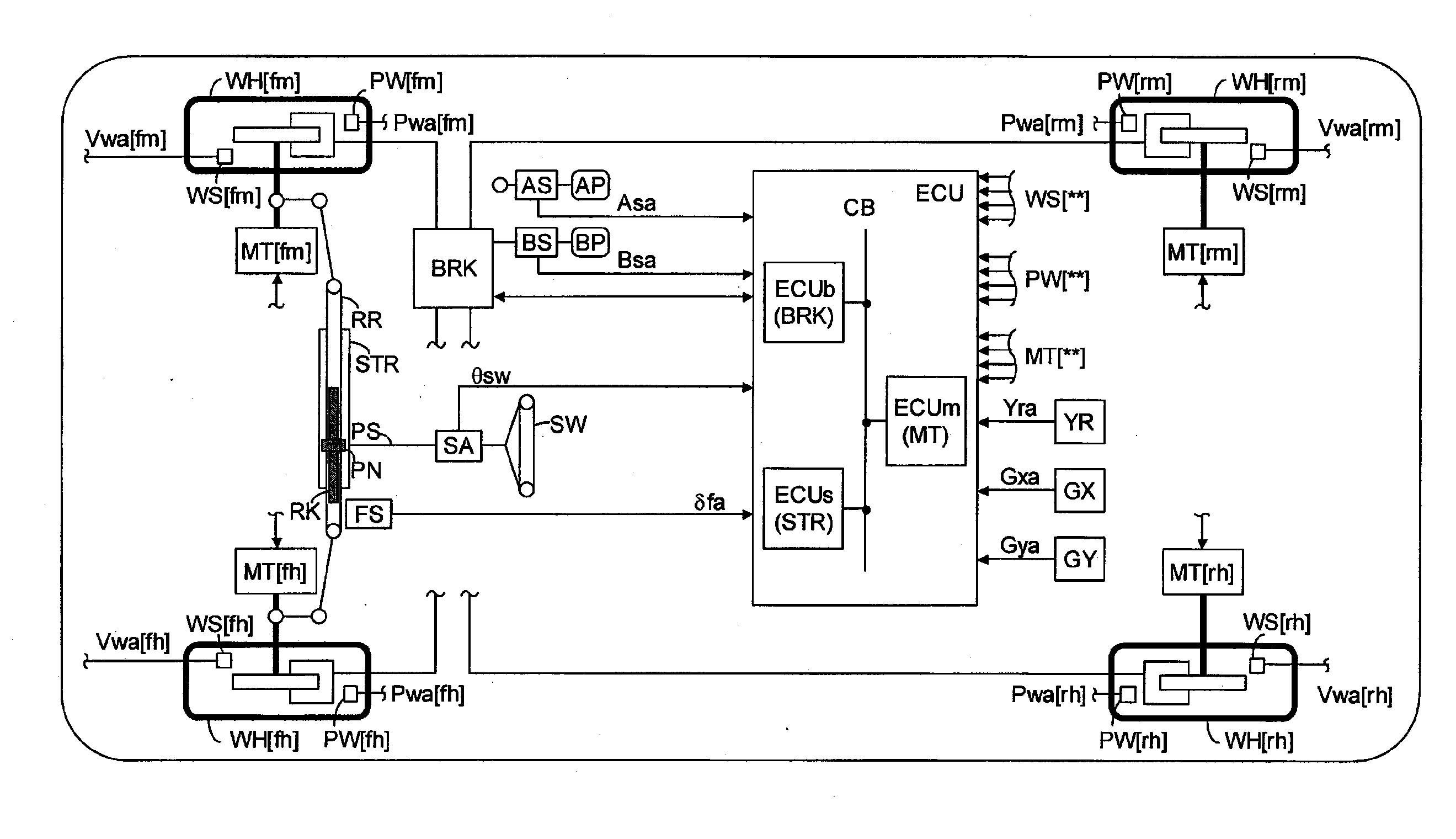
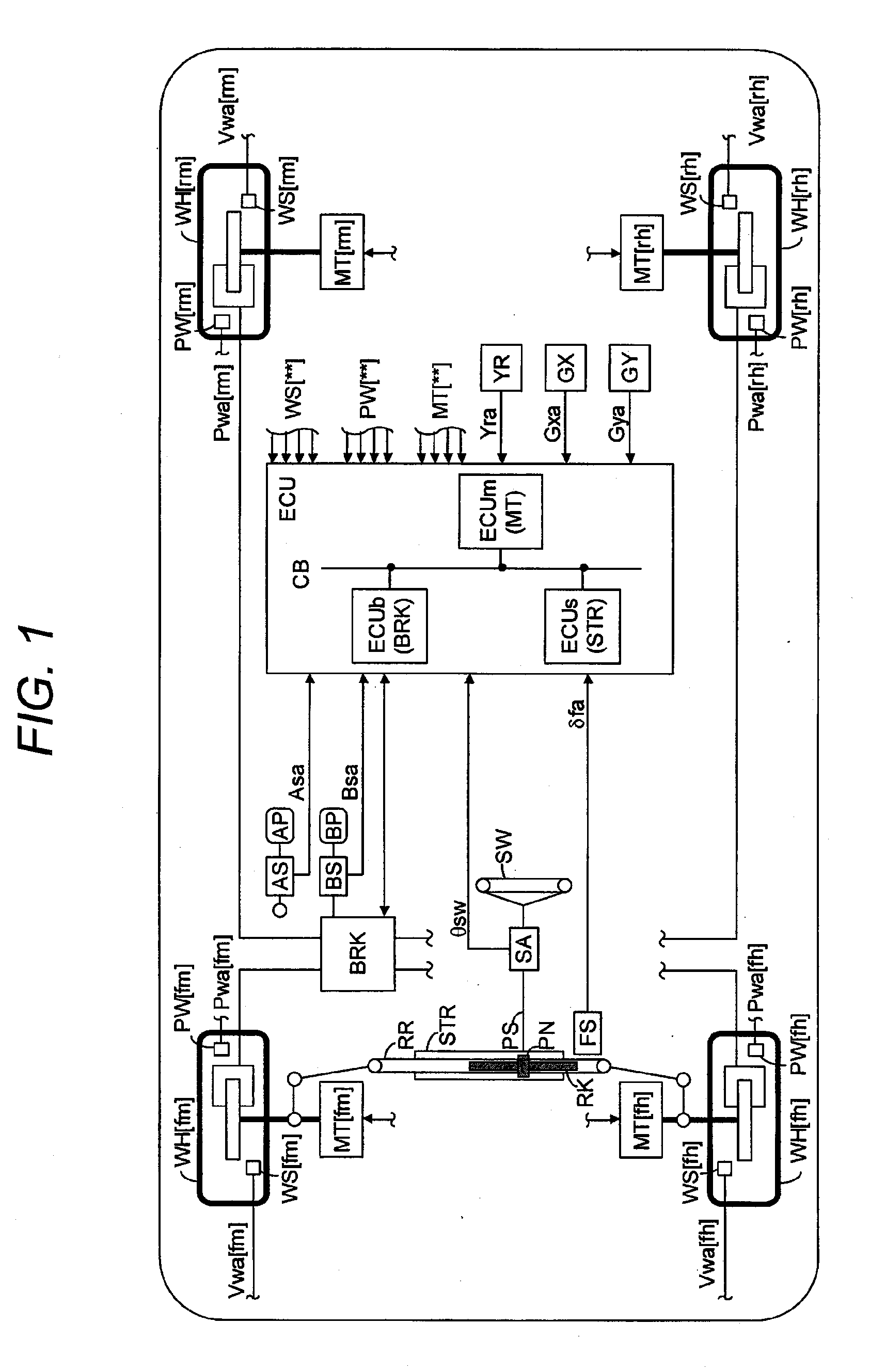
[0040]Hereinafter, a speed control device of a vehicle according to an illustrative embodiment of the present invention will be described with reference to the drawings. FIG. 1 is a diagram showing the overall configuration of a vehicle in which a speed control device of a vehicle according to the illustrative embodiment (hereinafter, also referred to as “a device”) is mounted. This vehicle is a four-wheel-drive vehicle including an electric motor (in-wheel motor) MT[**] serving as a driving source is incorporated in the tire wheel of each wheel WH[**]. That is, this vehicle is an in-wheel motor vehicle, and no differential is provided between the left and right front wheels, between the left and right rear wheels, and between the front wheels and the rear wheels.

[0041]The inventive concept of the present invention may be applied to a front-wheel-drive vehicle or a rear-wheel-drive vehicle. In the case of a front-wheel-drive vehicle, the electric motors MT[rm] and MT[rh] for the lef...


PUM


Abstract

A vehicle speed control device is provided. The device includes a steering device which steers left and right wheels, first and second electric motors which separately apply power to the left and right wheels, an operation amount acquisition unit which acquires an acceleration operation amount by the driver of the vehicle, a steering angle acquisition unit which acquires a steering angle which is a value between an inner wheel steering angle and an outer wheel steering angle; a vehicle speed acquisition unit configured to acquire an actual speed of the vehicle; and a control unit configured to control the first electric motor and the second electric motor on the basis of the acceleration operation amount, the actual speed, the steering angle, and a steering geometry indicating a geometric relationship between the steering angle and a turning center of the vehicle.

Description

CROSS REFERENCE TO RELATED APPLICATIONS[0001]This application is based on and claims priority under 35 U.S.C. §119 to Japanese Patent Application 2009-296919, filed on Dec. 28, 2009, the entire content of which is incorporated herein by reference.BACKGROUND[0002]1. Field of the Invention[0003]The present invention relates to a vehicle speed control device for adjusting a speed (vehicle speed) of a vehicle having electric motors serving as a power source for separately applying power to left and right wheels.[0004]2. Description of Related Art[0005]In a typical four-wheel vehicle, the axles of left and right wheels are mechanically connected to each other through a differential. Power obtained from a single power source (for example, an engine) is transmitted to the left and right wheels (driving wheels) through the differential. In a vehicle turning state, the action of the differential compensates the difference in the wheel speed between the wheels due to the difference in the mov...

Claims


Application Information

Patent Timeline
IPC IPC(8): B62D6/00B62D5/04
CPCB62D11/003Y02T10/7258B62D11/24Y02T10/72
Inventor YASUI, YOSHIYUKIAIZAWA, HIROAKI
Owner ADVICS CO LTD
Why Eureka
Try Eureka