Light emitting diode having electrode pads

Active Publication Date: 2011-07-07
SEOUL VIOSYS CO LTD
View PDF6 Cites 63 Cited by
  • Summary
  • Abstract
  • Description
  • Claims
  • Application Information

AI Technical Summary

Benefits of technology

[0012]Exemplary embodiments of the present invention provide a light

Problems solved by technology

This may be referred to as current crowding, and may lead to a reduction in light emitting area, thereby deteriorating luminous efficacy of the light emitting source.
However, since the transparent electrode layer tends to absorb light, the thickness of the transparent electrode layer may be limited, thereby providing limited current spreading.
In particular, in a large LED having an area of about 1 mm2 or more for high output, there may be a limit in achieving efficient current spreading thr

Method used


Image

  • Light emitting diode having electrode pads
  • Light emitting diode having electrode pads
  • Light emitting diode having electrode pads

Examples


Example

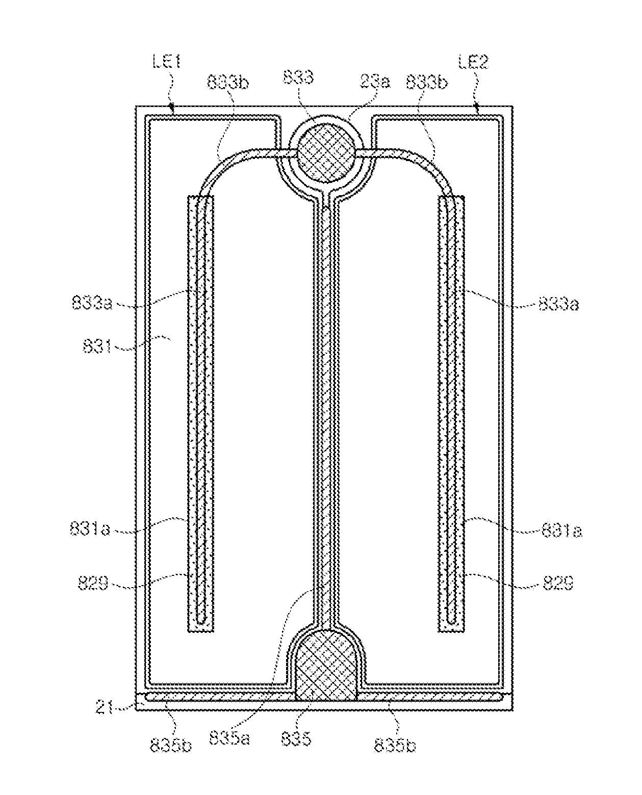
[0106]As in the sixth and seventh embodiments, a second electrode pad 163 is disposed at the center of the substrate 21. The second electrode pad 163 may be located on a first conductive type semiconductor layer 23 with an insulation layer 31 interposed therebetween.

[0107]Upper extensions 163a are located on each of the light emitting regions LE1, LE2, LE3, LE4. The upper extensions 163a may extend along edges of each of the light emitting regions LE1, LE2, LE3, LE4 and be connected to a second conductive type semiconductor layer 27 or a transparent electrode layer 29. The upper extensions 163a are connected to the second electrode pad 163 through connectors 163b, which are insulated from the light emitting regions LE1, LE2, LE3, LE4 by the insulation layer 31.

[0108]According to the present exemplary embodiment, with the second electrode pad 163 located at the center of the substrate 21, a light emitting region is divided into the plural light emitting regions LE1, LE2, LE3, LE4, so...


PUM


Abstract

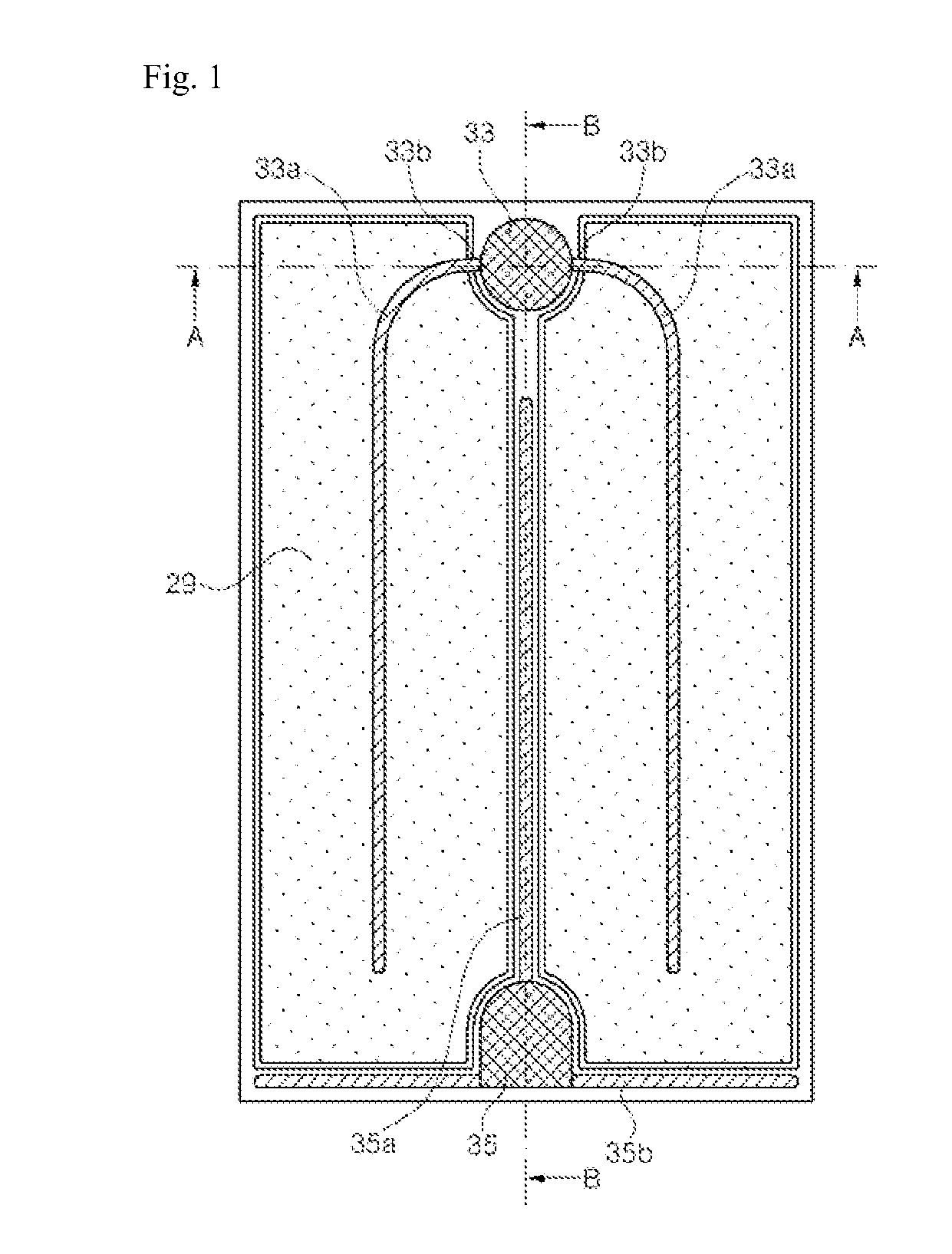
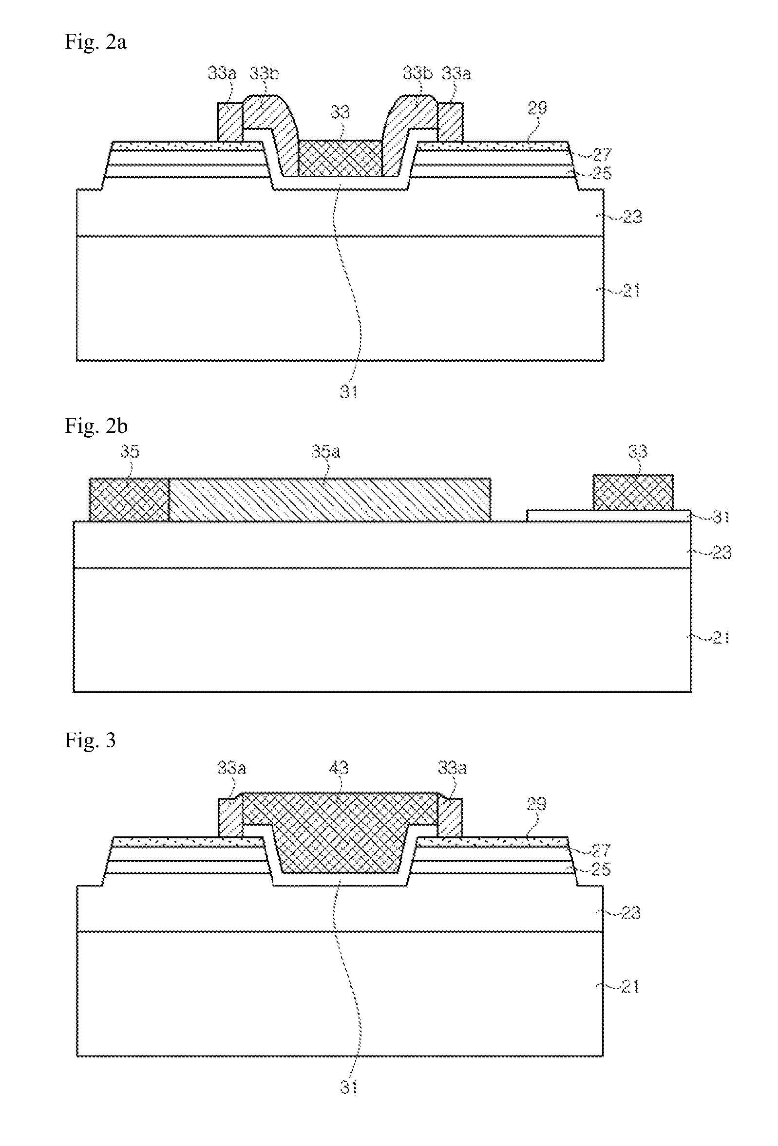
Exemplary embodiments of the present invention relate to a including a substrate, a first conductive type semiconductor layer arranged on the substrate, a second conductive type semiconductor layer arranged on the first conductive type semiconductor layer, an active layer disposed between the first conductive type semiconductor layer and the second conductive type semiconductor layer, a first electrode pad electrically connected to the first conductive type semiconductor layer, a second electrode pad arranged on the second conductive type semiconductor layer, an insulation layer disposed between the second conductive type semiconductor layer and the second electrode pad, and at least one upper extension electrically connected to the second electrode pad, the at least one upper extension being electrically connected to the second conductive type semiconductor layer.

Description

CROSS-REFERENCE TO RELATED APPLICATIONS[0001]This application claims priority from and the benefit of Korean Patent Application No. 10-2010-0001089, filed on Jan. 7, 2010, Korean Patent Application No. 10-2010-0001090, filed on Jan. 7, 2010, Korean Patent Application No. 10-2010-0001204, filed on Jan. 7, 2010, Korean Patent Application No. 10-2010-0001205, filed on Jan. 7, 2010, Korean Patent Application No. 10-2010-0001408, filed on Jan. 7, 2010, Korean Patent Application No. 10-2010-0001813, filed on Jan. 8, 2010, Korean Patent Application No. 10-2010-0003396, filed on Jan. 14, 2010, Korean Patent Application No. 10-2010-0003964, filed on Jan. 15, 2010, and Korean Patent Application No. 10-2010-0003965, filed on Jan. 15, 2010, which are hereby incorporated by reference for all purposes as if fully set forth herein.BACKGROUND OF THE INVENTION[0002]1. Field of the Invention[0003]Exemplary embodiments of the invention relate to light emitting diodes and, more particularly, to light e...

Claims


Application Information

Patent Timeline
IPC IPC(8): H01L33/42H01L33/36
CPCH01L33/08H01L33/20H01L33/38H01L33/44H01L33/385H01L2924/0002H01L33/42H01L33/62H01L2924/00H01L2933/0016H01L33/32H01L33/387
Inventor SEO, WON CHEOLKAL, DAE SUNGYE, KYUNG HEEKIM, KYOUNG WANYOON, YEO JIN
Owner SEOUL VIOSYS CO LTD
Why Eureka
Try Eureka