Adverse Pressure Gradient Seal Mechanism

a gradient seal and gradient technology, applied in the direction of engine seals, leakage prevention, machines/engines, etc., can solve the problems of increased clearance, direct impact on overall turbine performance and efficiency, and increased leakage flow, so as to reduce the leakage flow

Inactive Publication Date: 2011-07-07
GENERAL ELECTRIC CO
View PDF27 Cites 10 Cited by
  • Summary
  • Abstract
  • Description
  • Claims
  • Application Information

AI Technical Summary

Benefits of technology

[0006]The present application further provides for a method of limiting a leakage flow through variable speed surfaces. The method may include the steps of positioning a number of labyrinth teeth on one of the variable speed surfaces, positioning an adverse pressure gradient seal between a pair of the labyrinth teeth, rotating the variable speed surfaces, producing an adverse pressure gradient about the adverse pressure gradient seal, and reducing the leakage flow across the variable speed surfaces.

Problems solved by technology

Steam bypassing either the nozzles or the buckets due to inter-stage leakage, tip leakage, packing leakage, and other leakage flows are concerns in the turbo-machinery industry given that they do not produce power.
Moreover, such leakage flows also may disrupt the flow through the nozzles and buckets so as to decrease turbine shaft output and directly impact overall turbine performance and efficiency.
These leakage flows generally are caused by increased clearances between the rotating and the stationary components.
The increased clearances may be caused by rubbing, solid particle erosion, foreign object damage, and the like.
Leakage through such labyrinth seals, however, still may be a significant percentage of the overall main flow even in the best of conditions.

Method used


Image

  • Adverse Pressure Gradient Seal Mechanism
  • Adverse Pressure Gradient Seal Mechanism
  • Adverse Pressure Gradient Seal Mechanism

Examples


Embodiment Construction

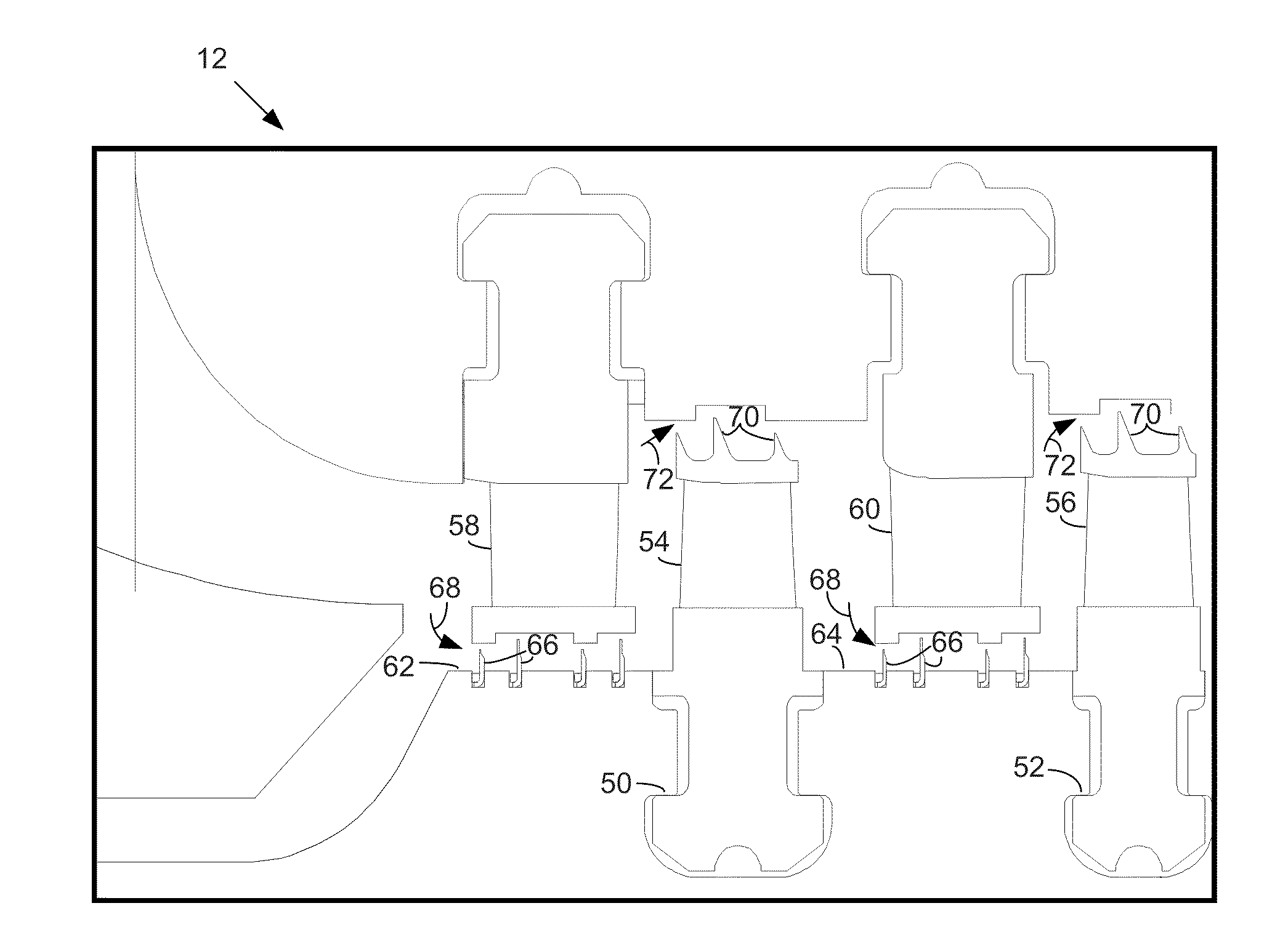
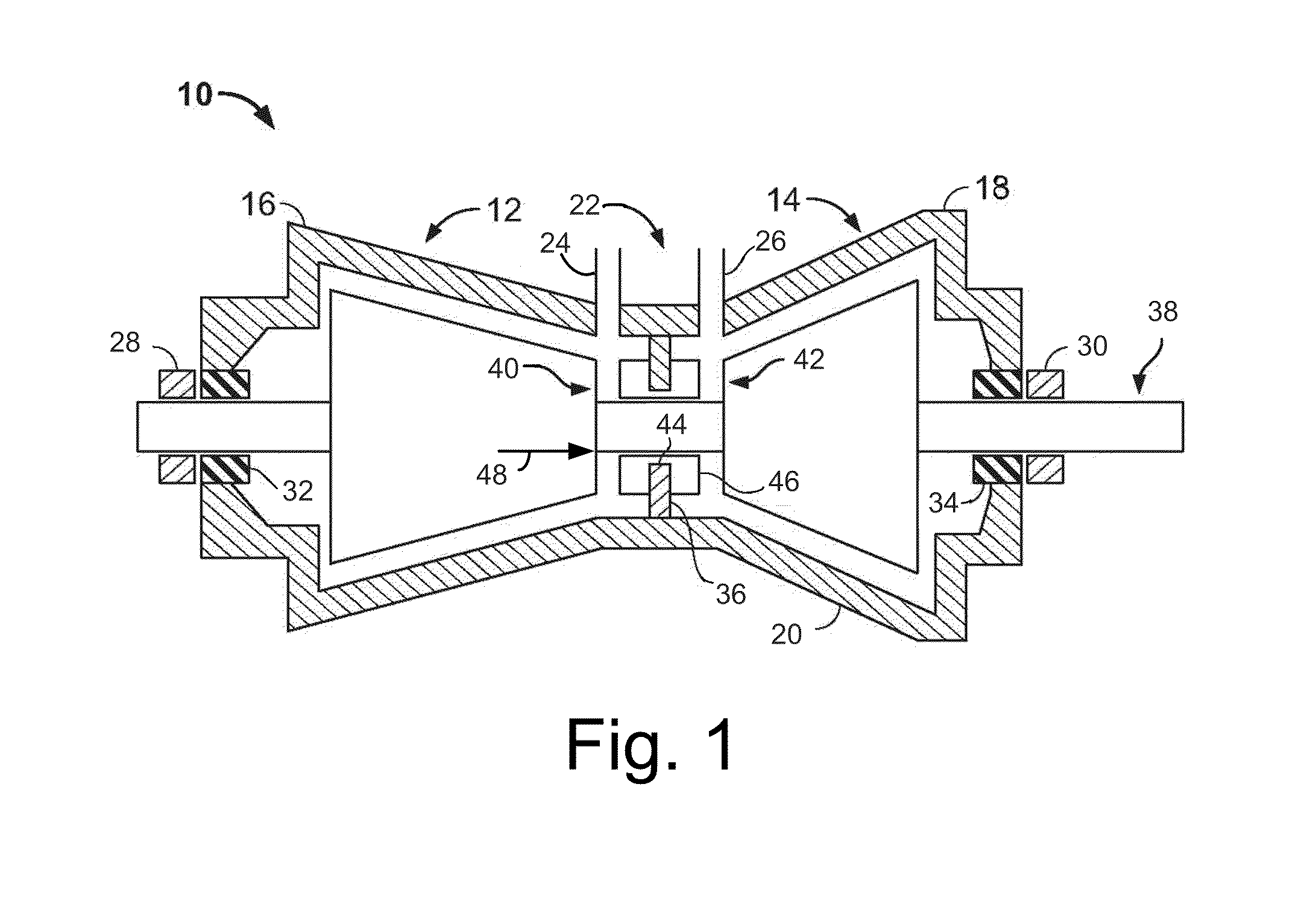
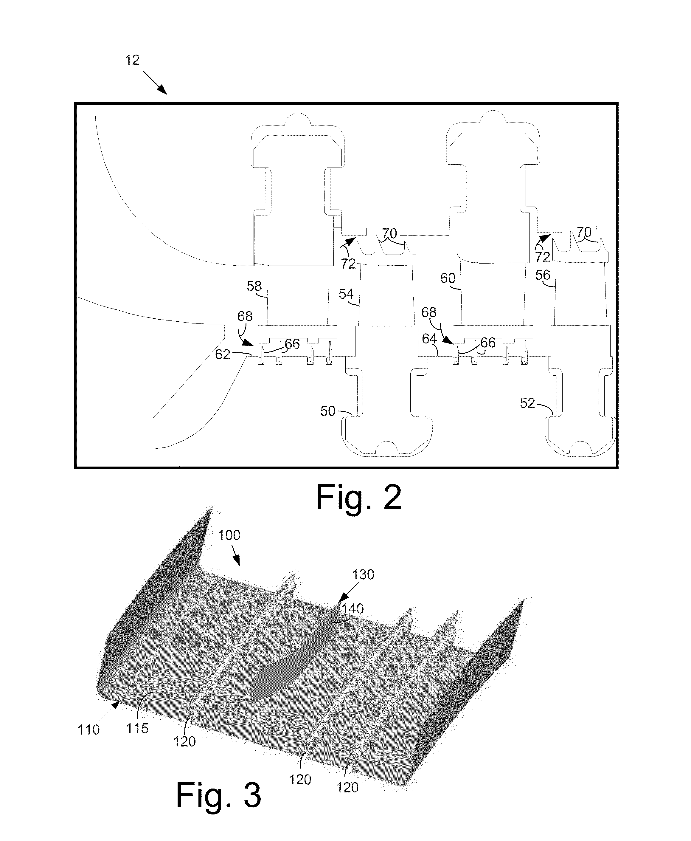
[0013]Referring now to the drawings, in which like numerals refer to like elements throughout the several views, FIG. 1 is a schematic view of an example of a known steam turbine 10 as may be used herein. The steam turbine 10 may include a high pressure (“HP”) section 12 and an intermediate pressure (“IP”) section 14. An outer shell or casing 16 may be divided axially into upper and lower half sections 18, 20 respectively and span both the HP section 12 and the IP section 14. A central section 22 of the casing 16 may include a high pressure steam inlet 24 and an intermediate pressure steam inlet 26. Within the casing 16, the HP section 12 and the IP section 14 may be arranged in a single bearing span supported by an HP journal bearing 28 and an IP journal bearing 30. An HP steam seal unit 32 and an IP steam seal unit 34 are located inboard of each journal bearing 28, 30, respectively.

[0014]Although the examples described herein are in the context of the HP section 12 and the IP sect...


PUM


Abstract

An adverse pressure gradient seal mechanism for use with variable speed components. The adverse pressure gradient seal mechanism may include a number of labyrinth teeth positioned on a component and an adverse pressure gradient seal positioned between a pair of the labyrinth teeth. The adverse pressure gradient seal may include a number of strips with each of the strips having an angled end.

Description

TECHNICAL FIELD[0001]The present application relates generally to steam turbines and gas turbines and more particularly relates to an adverse pressure gradient seal mechanism for leakage flow control in cavities involving variable speed surfaces.BACKGROUND OF THE INVENTION[0002]In order for a turbine to produce shaft power, steam must pass through both the nozzle and bucket flow passages. Steam bypassing either the nozzles or the buckets due to inter-stage leakage, tip leakage, packing leakage, and other leakage flows are concerns in the turbo-machinery industry given that they do not produce power. Moreover, such leakage flows also may disrupt the flow through the nozzles and buckets so as to decrease turbine shaft output and directly impact overall turbine performance and efficiency. These leakage flows generally are caused by increased clearances between the rotating and the stationary components. The increased clearances may be caused by rubbing, solid particle erosion, foreign ...

Claims


Application Information

Patent Timeline
Patent Type & Authority Applications(United States)
IPC IPC(8): F16J15/447
CPCF16J15/4472F01D11/02
Inventor BHAGAVATHEESWARAN, ANANTHA PADMANABHANKASIBHOTLA, RAVI SHANKAR VENKATAPRUTHI, ROHIT
Owner GENERAL ELECTRIC CO
Why Eureka
Try Eureka