Tapered type connector for a flexible tube
- Summary
- Abstract
- Description
- Claims
- Application Information
AI Technical Summary
Benefits of technology
Problems solved by technology
Method used
Image

Examples
Embodiment Construction
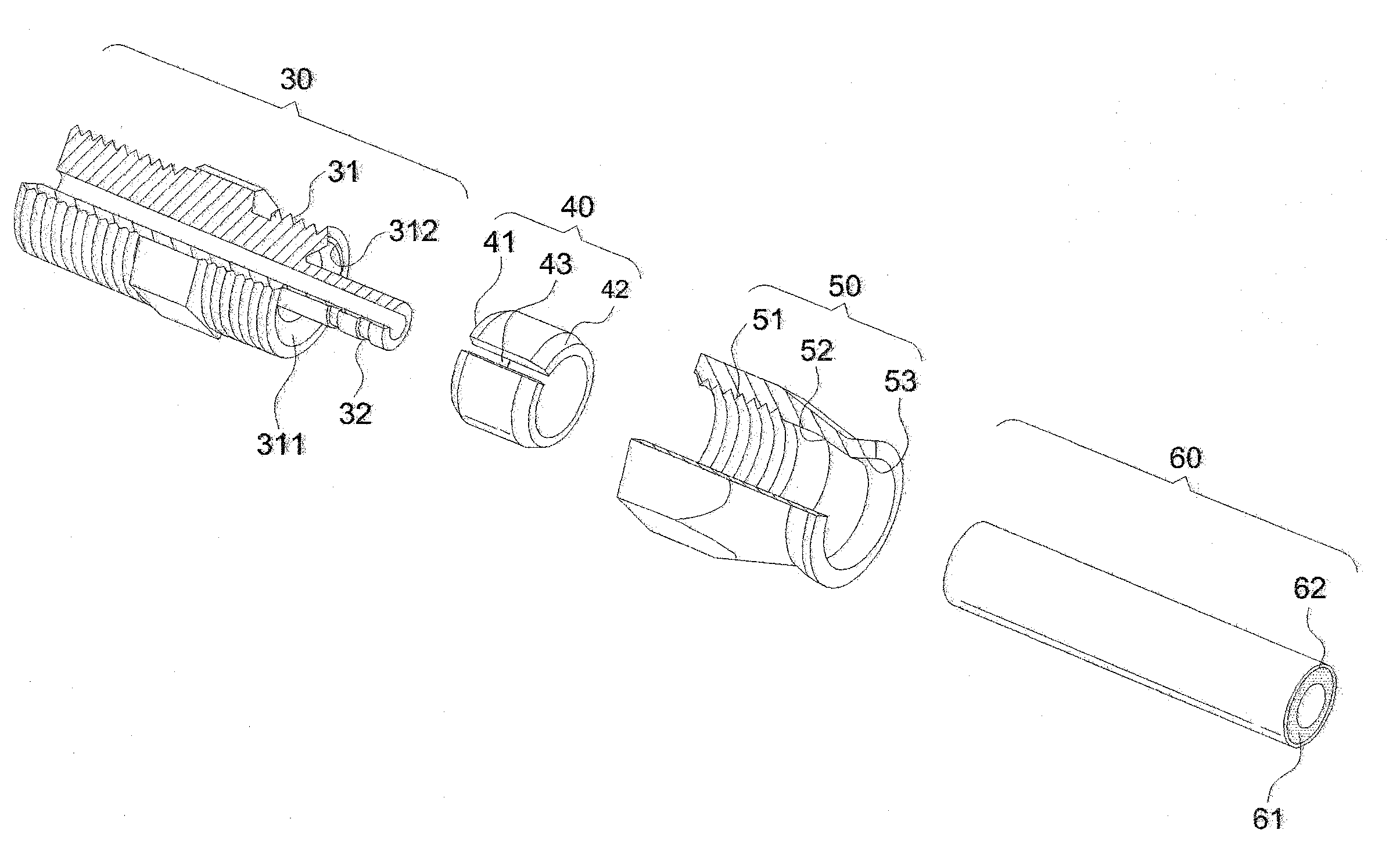
[0019]First of all, referring to FIGS. 4 through 7, the invention includes a coupling body 30, a clamp ring 40 and a clamp nut 50.
[0020]The coupling body 30 includes an external threaded portion 31 and a stranded portion 32 at one side thereof. An annular cavity 311 is formed in the external threaded portion 31 such that the stranded portion 32 is extended into the annular cavity 311. The defining wall of the annular cavity 311 is tapered inward to form a first external fastening cone 312. The end portion of the flexible tube 60 fits over the stranded portion 32.
[0021]The clamp ring 40 includes at the internal end thereof a fist internal fastening cone 41 facing to the first external fastening cone 312 of the coupling body 30 and at the external end thereof a second internal fastening cone 42. Moreover, a clamp indentation 43 is formed axially in the clamp ring 40. The clamp ring 40 slips over the periphery of the outer end of the flexible tube 60.
[0022]The clamp nut 50 includes an ...
PUM
 Abstract
Description
Claims
Application Information