Antenna system comprising an electrically small antenna for reception of UHF band channel signals

Inactive Publication Date: 2011-07-07
THOMSON LICENSING SA
View PDF10 Cites 10 Cited by
  • Summary
  • Abstract
  • Description
  • Claims
  • Application Information

AI Technical Summary

Benefits of technology

[0021]The concept of the invention will enable through the addition of an active impedance matching device to guarantee a level of performance of the electrically small antennas over the entire UHF band thus permitting an optimal level of sensitivity. Also the addition of a network of rejecter filters that can be tuned, managed by the processor of the terminal will ensure a management of potential interferences from the upper part of the UHF spectrum while conserving the possibilities for reception of new services proposed in this frequency zone.

Problems solved by technology

But the programmed appearance of Internet access services in the upper part of the UHF spectrum clearly poses the problem of cohabitation in terms of interferences with the DVB_T or DVB_H standard reception services.
Extra flat terminals thus integrating an antenna inside their cover of which some cover 4 to 5 frequency bands and wide band antennas generally have mediocre levels of performance and remain relatively bulky whereas quality antennas are small but of narrow band.
The use of the UHF band located from 470 to 862 MHz renders the design of miniature antennas more delicate.
As a consequence the performances in terms of efficiency are mediocre.
However this concept known as the Linvill concept is only valid at low frequency.

Method used


Image

  • Antenna system comprising an electrically small antenna for reception of UHF band channel signals
  • Antenna system comprising an electrically small antenna for reception of UHF band channel signals
  • Antenna system comprising an electrically small antenna for reception of UHF band channel signals

Examples


Embodiment Construction

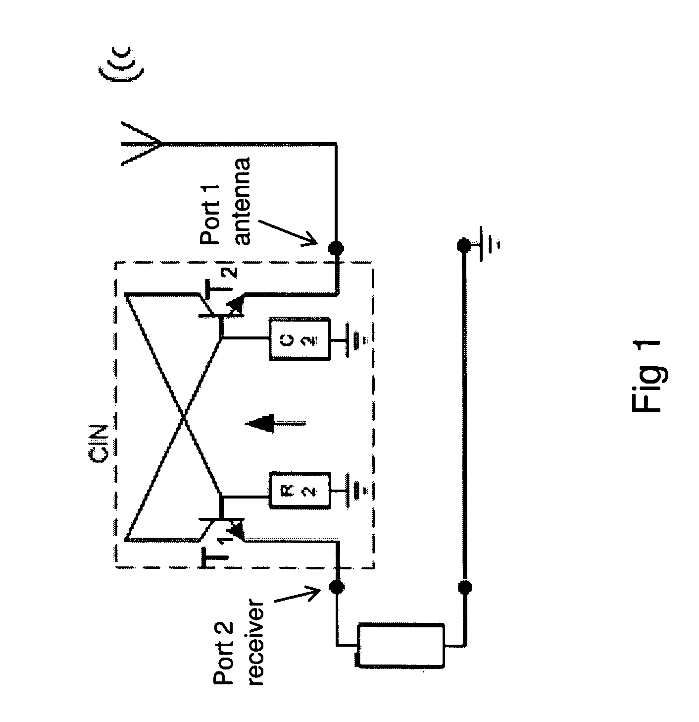
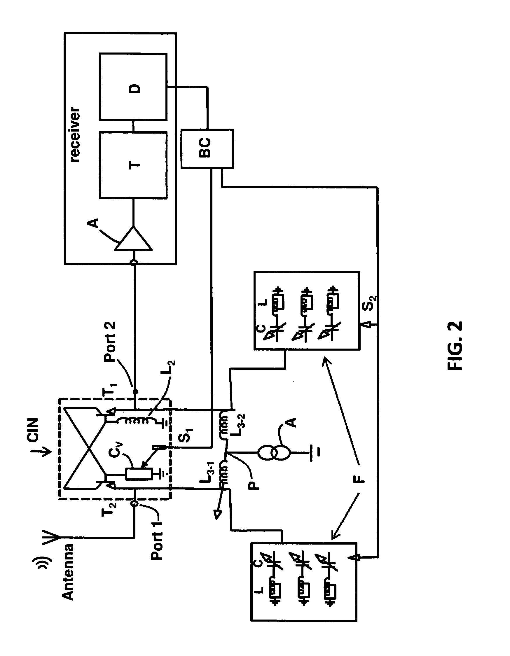
[0029]FIG. 2 describes the principle of the invention. An antenna system according to the invention thus comprises an electrically small antenna in which the input port 1 is connected via the port 2 of an impedance matching device to a receiver for the reception of UHF band channel signals via a standard receiver for example a DVB-H receiver itself comprising an amplifier A, a tuner element T and a demodulator D.

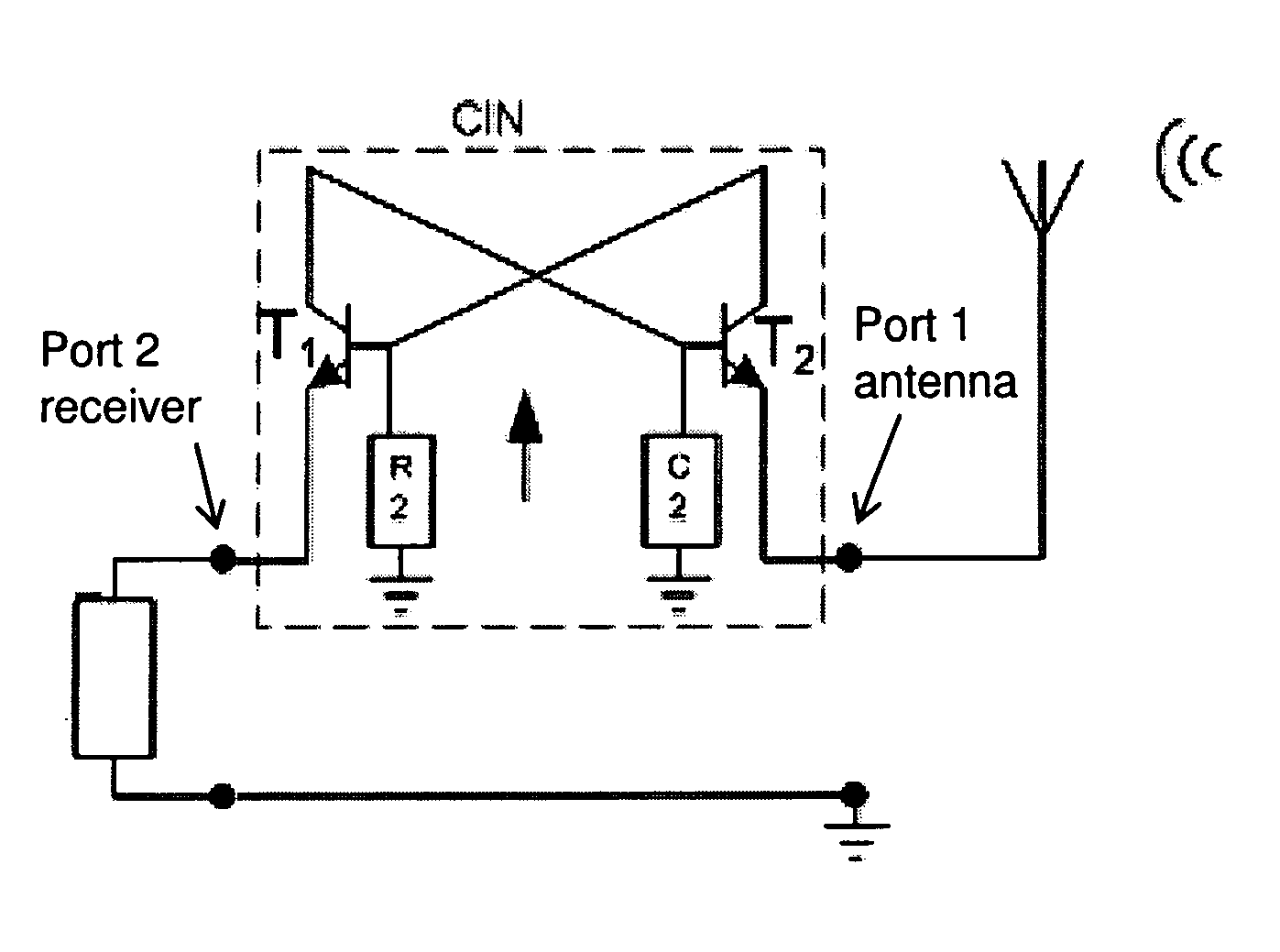
[0030]The impedance matching device is firstly formed by a digital impedance converter CIN as described with the aid of FIG. 1 and comprising the addition of an inductance L2 connected to the base of the transistor T1 that enables both a gain in the frequencies limit of the UHF band to be realised, for example a gain of 6 to 8 dB, and also enables the capacitive compensation to be made linear according to the frequency of the signal received.

[0031]A variable capacity Cv replaces the capacity C2 of the negative impedance converter CIN as described with FIG. 1. It is controlle...


PUM


Abstract

The invention relates to an antenna system for reception of channel signals from the UHF band by a receiver, comprising an electrically small antenna.The system also comprises, connected between the port connected to the antenna and that of the receiver, an active impedance matching device controlled by command signals depending on the quality of the signal received by the receiver to compensate for the impedance variations due to the environment associated with the antenna and to reject the frequencies of interfering channels adjacent to the reception channel without interfering with the active impedance matching of the antenna.

Description

[0001]The present invention relates to an antenna system comprising an Electrically Small Antenna (ESA) for reception of UHF band channel signals.BACKGROUND OF THE INVENTION[0002]The present invention enables use from the lower part of the spectral zone to 1 GHz in the liberated upper part of the UHF (Ultra High Frequency) In fact this zone was previously used for broadcasting television in analogue. The passage of television broadcasting from analogue to digital has thus liberated this zone. These frequencies are dedicated to audiovisual broadcasters to implement High Definition (HD) broadcast services and to mobile operators for the purpose of launching access services to the Internet via cell networks. Their positioning in the UHF spectrum at less than 1 GHz ensures a long range and good penetration in buildings.[0003]But the programmed appearance of Internet access services in the upper part of the UHF spectrum clearly poses the problem of cohabitation in terms of interferences ...

Claims


Application Information

Patent Timeline
IPC IPC(8): H04W88/02
CPCH01Q9/02H03J7/04H03H11/30
Inventor ROBERT, JEAN-LUCMINARD, PHILIPPEPRAHO, BRICE
Owner THOMSON LICENSING SA
Why Eureka
Try Eureka