
Active marker device for use in electromagnetic tracking system

a technology of active marker and tracking system, which is applied in the field of active marker device for electromagnetic tracking system, can solve the problems of not being addressed by these devices, the expense created by having relatively expensive electromagnetic sensors and cables permanently embedded, and the combination of electronic cables required is relatively expensive. to achieve the effect of being easily imaged

Active Publication Date: 2011-07-07
CIVCO MEDICAL INSTR CO
View PDF6 Cites 34 Cited by
  • Summary
  • Abstract
  • Description
  • Claims
  • Application Information

AI Technical Summary

Benefits of technology

[0013]In accordance with one aspect of the invention there is provided a marker device for use in an image-guided procedure on a patient. The marker device comprises an EM sensor, a frame assembly and releasably securable attachment members, e.g., adhesive disks. Each disk is arranged to be releasably (e.g., adhesively) secured to the skin of a patient and to be coupled to the frame assembly to secure the frame...

Problems solved by technology

These powered sensors typically provide position and orientation data sets of 5 or 6 degrees-of-freedom (DOF) and combined with the electronic cables required are relatively expensive.
However, two problems are not addressed by these devices.
One is the expense created by having the relatively expensive electromagnetic sensors and cables permanently embedded in these component markers that must be disposed of after a single use to avoid patient-to-patient contamination.
The second is the inability to place, remove and then replace the marker in the same location on a patient at a different time.

Method used


Image

  • Active marker device for use in electromagnetic tracking system
  • Active marker device for use in electromagnetic tracking system
  • Active marker device for use in electromagnetic tracking system

Examples


Embodiment Construction

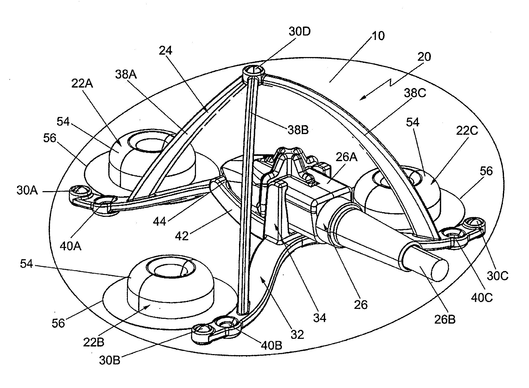
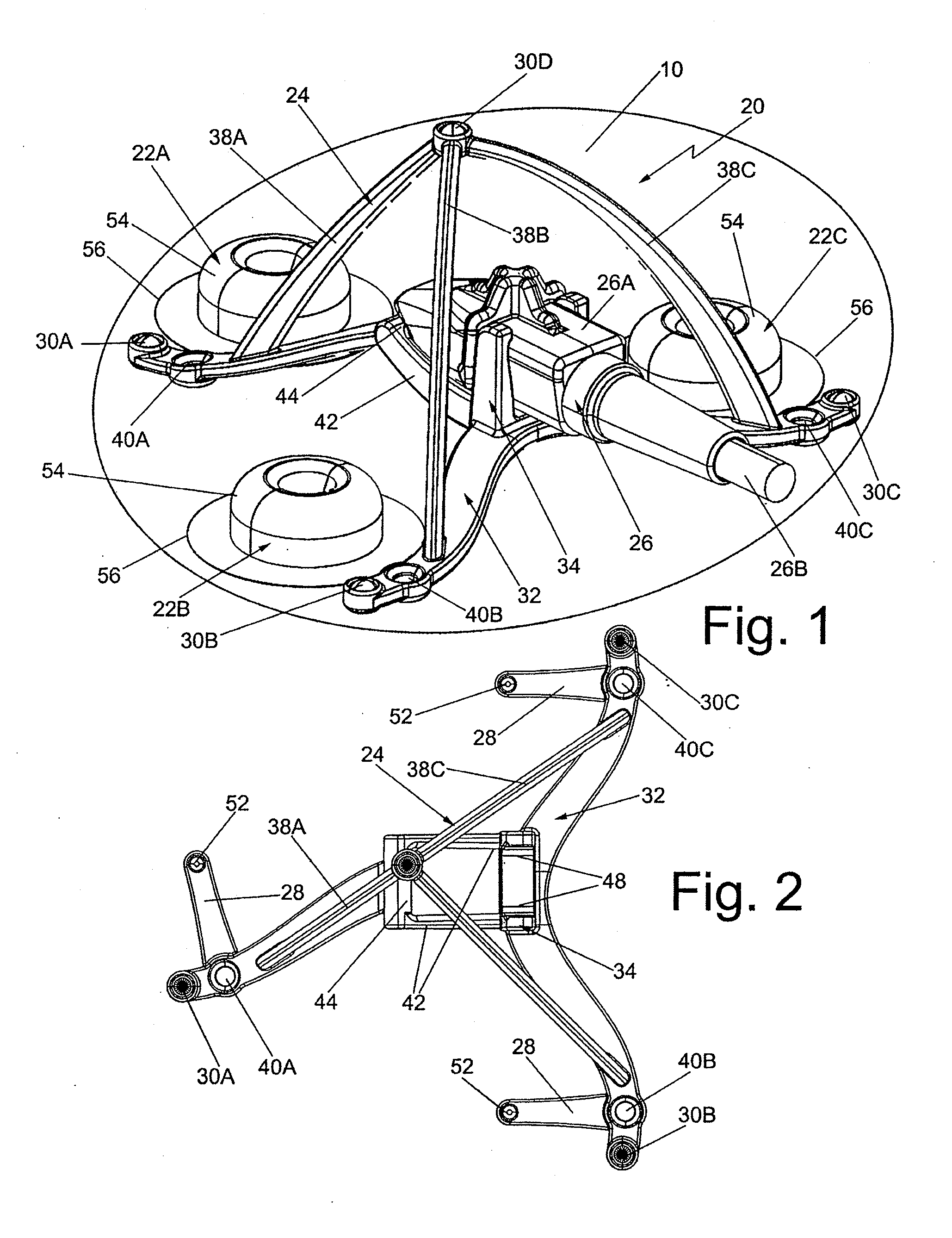
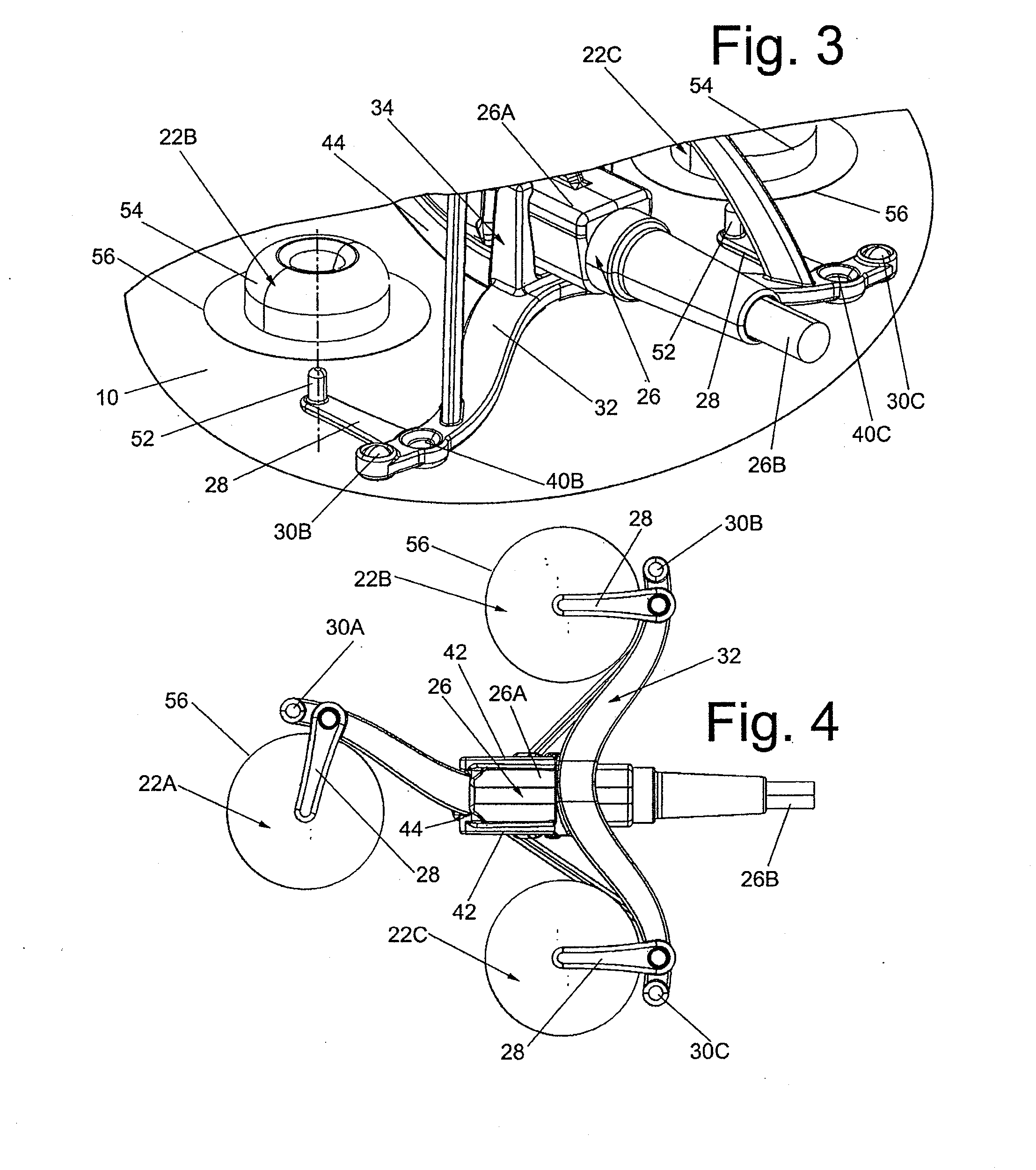
[0030]Referring now to the various figures of the drawing wherein like reference characters refer to like parts, there is shown in FIG. 1 an active marker device 20 constructed in accordance with this invention for use in an EM tracking system (not shown). The device 20 basically comprises a plurality of releasably securable attachment members, e.g., adhesive disks, 22A, 22B and 22C, a frame assembly 24 and an EM sensor assembly 26. The details of the frame assembly 24 and the sensor assembly 26 will be described later. Suffice it for now to state that in the exemplary embodiment shown the sensor assembly 26 includes a 6DOF electromagnetic sensor (not shown) contained in a particularly shaped housing 26A (FIGS. 1, 8 and 9). The frame assembly 24 includes a plurality of extension members 28 (to be described later) to which respective ones of the adhesive disks 22A, 22B and 22C may be releasably secured.

[0031]The device 20 is arranged to be releasably secured to the skin 10 of the pat...


PUM


Abstract

A device for use in an image-guided procedure on a patient is disclosed. The device includes an EM sensor assembly, a frame assembly (e.g., a base portion from which a plurality of legs project upward to a common point) and a plurality of attachment members. Each attachment member is arranged to be releasably (e.g., adhesively) secured to the skin of a patient and to be coupled to the frame assembly to secure the frame assembly on the skin of the patient. The EM sensor assembly is arranged to be releasably secured to the frame assembly (e.g., pivotably snap-fit into a socket in the frame assembly). The device additionally includes plural visualizable elements (e.g., metal balls) that are adapted to be readily imaged to establish imaging reference points and a plurality of asymmetrically disposed apertures to enable tattooing indicia on the skin of the patient through the apertures.

Description

CROSS-REFERENCE TO RELATED APPLICATIONS[0001]This utility application claims the benefit under 35 U.S.C. §119(e) of Provisional Application Ser. No. 61 / 292,586 filed on Jan. 6, 2010 and entitled Active Marker for Use in Electromagnetic Tracking System, the entire disclosure of which is incorporated by reference herein.FIELD OF THE INVENTION[0002]This invention relates generally to medical instrument tracking systems and more particularly active marker devices for use in electromagnetic (EM) field multidimensional tracking systems involving the use of medical images (both 2-D and 3-D data sets of real time and / or delayed and / or fused images) to register to a patient.BACKGROUND OF THE INVENTION[0003]As is known, optical and electromagnetic tracking (EMT) technologies are two non-mechanical, real-time, approaches for accurate medical instrument tracking and navigation using appropriately registered volume images (digital data sets). Both optical and electromagnetic technologies have ad...

Claims


Application Information

Patent Timeline
IPC IPC(8): A61B5/05
CPCA61B19/54A61B2017/00951A61B2019/5495A61B2019/5483A61B2019/5251A61B2090/3983A61B2090/3995A61B2034/2051A61B90/39
Inventor WHITMORE, III, WILLET F.WILSON, ROGER F.
Owner CIVCO MEDICAL INSTR CO
Learn More