Auxiliary power driven unit for a bicycle

a technology of auxiliary power and drive unit, which is applied in the direction of rider propulsion, vehicle components, transportation and packaging, etc., can solve the problems of difficult engagement or disengagement of the drive unit from the bicycle, the unit is often difficult to mount to the bicycle, and the unit is difficult to mount and use external tools. the effect of significant time and external tools

Inactive Publication Date: 2011-07-14
DUIGNAN MICHAEL DALE
View PDF15 Cites 24 Cited by
  • Summary
  • Abstract
  • Description
  • Claims
  • Application Information

AI Technical Summary

Benefits of technology

[0007]According to an embodiment, the powered friction-driving device can be used on a bicycle with or without a suspension system and can accommodate wheel movement due to uneven road surfaces. The device can be removed and re-in

Problems solved by technology

However, prior friction drive units are typically rather large and bulky, occupying significant space around or near the bicycle frame, and offsetting the center of gravity and balance of the bicycle.
These drive units are often difficult to engage or disengage from the bicycle.
Mounting the unit to the bicycle requires significant time and the use of external tools.
Upon reaching a destination, the drive unit cannot be easily removed to store the bicycle.
Some drive

Method used


Image

  • Auxiliary power driven unit for a bicycle
  • Auxiliary power driven unit for a bicycle
  • Auxiliary power driven unit for a bicycle

Examples


Embodiment Construction

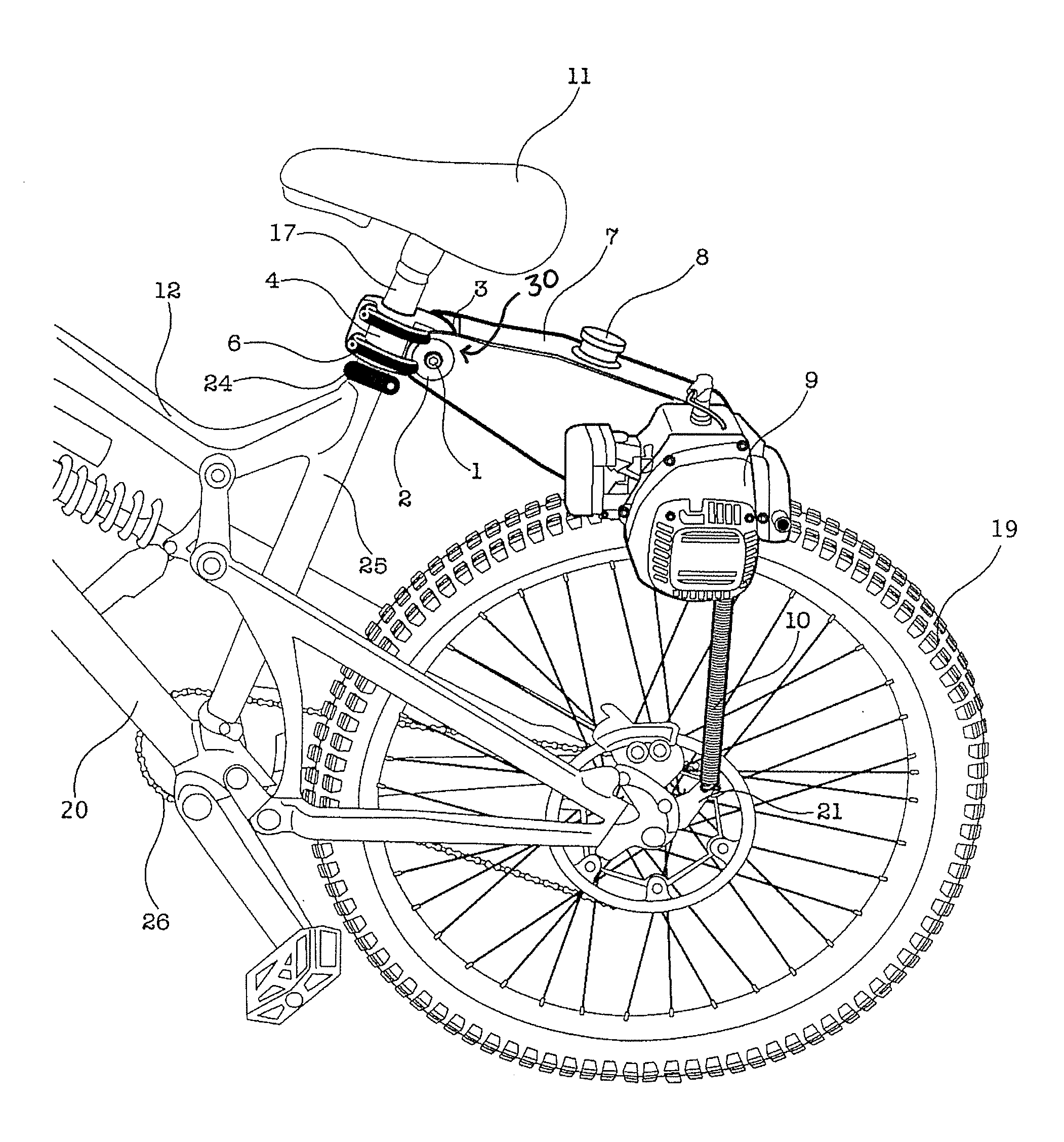
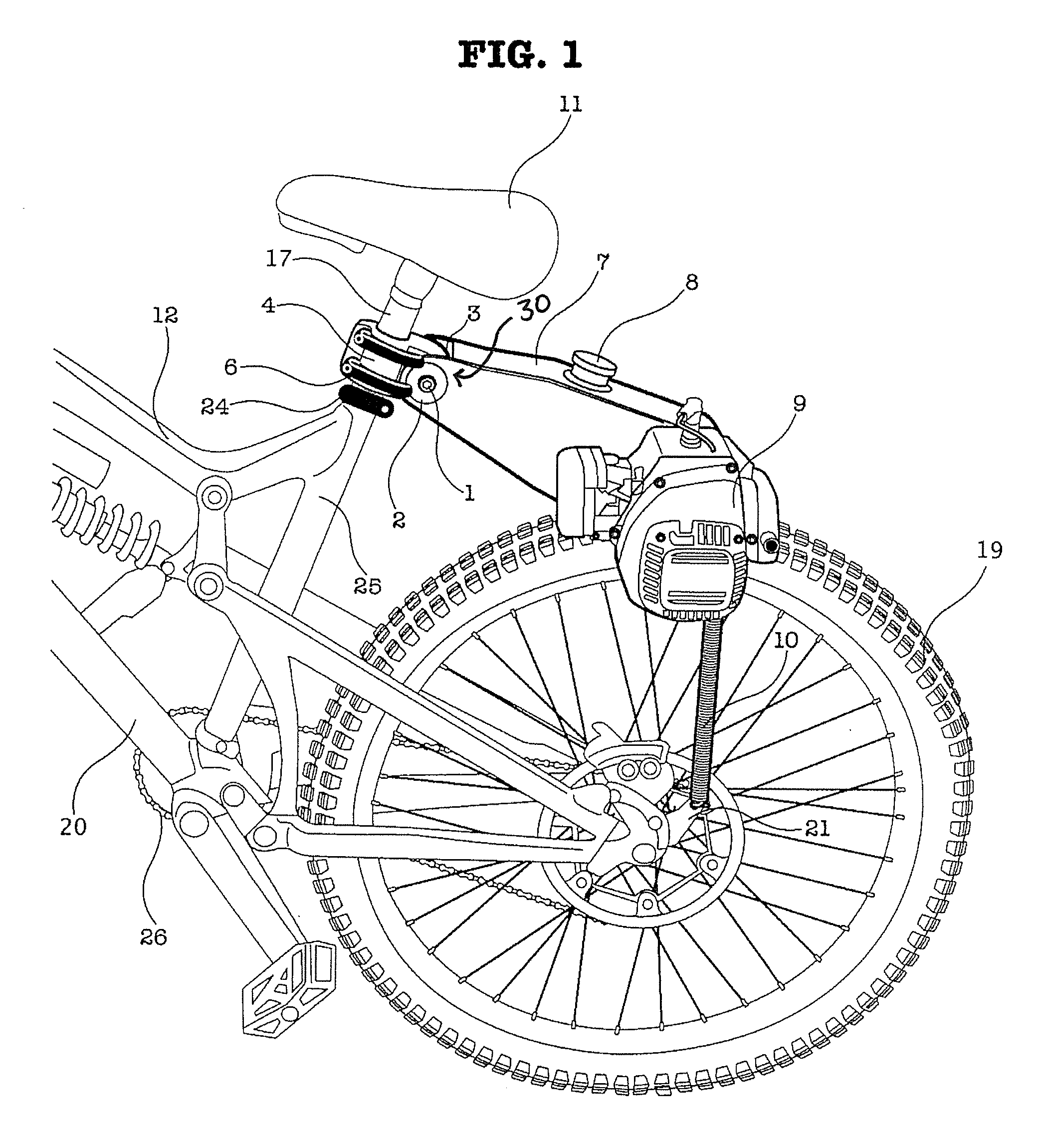
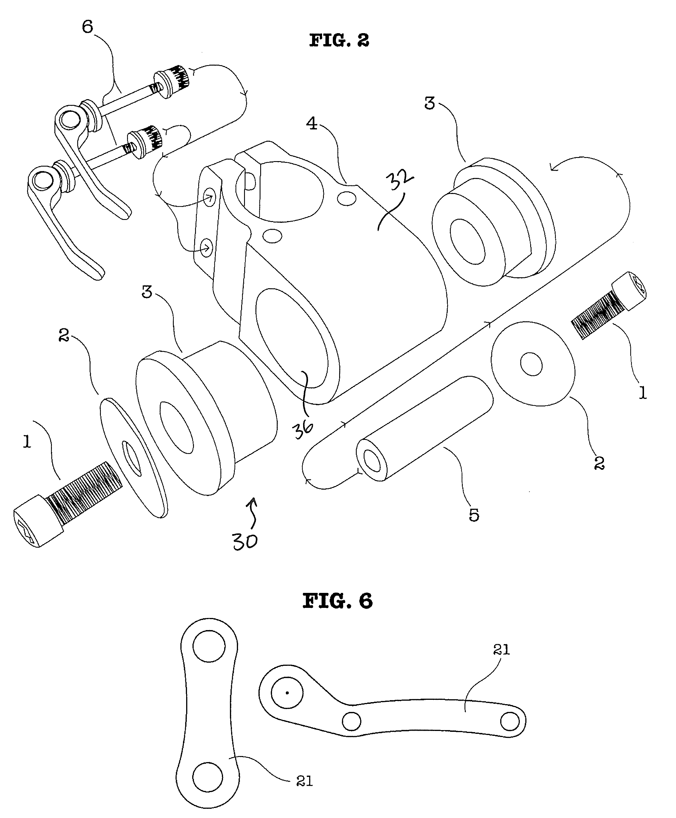
[0017]This invention relates to an auxiliary drive system for vehicles, and more particularly to a motor drive for a conventional or suspension-based pedal-operated bicycle. The drive system includes a motor configured to frictionally drive the rear wheel of the bicycle, and a clamp that attaches to the seat post of the bicycle. A pivotal joint is connected between the clamp and the motor. This joint enables the motor to pivot up and down relative to the clamp, pivoting about a horizontal axis. This pivoting movement enables the drive system to accommodate a bicycle with a rear suspension, which allows the rear wheel to move with respect to the seat post. When the bicycle encounters bumps, dips, or other surface irregularities, the rear suspension enables the rear wheel to move up or down relative to the bicycle seat. To accommodate this suspension, the drive system includes the horizontal joint that allows the motor to move with the rear wheel, relative to the clamp mounted to the ...


PUM


Abstract

An auxiliary, removable, modular power drive unit has a pivot point that can be attached to any bicycle or vehicle by way of a quick release clamp system. The power for the drive system may be derived from an internal combustion engine or electric motor. The power developed by the engine or motor is delivered to the rear wheel of a bicycle by a friction drive wheel that presses directly onto the tire of the bicycle. The power unit may utilize a clamp joined to an integrated fuel cell by a pivot point, causing the fuel cell to act as a swing arm and a motor mount. This enables the fuel cell to move up and down to compensate for different tire sizes, variations in road conditions, or movement of a suspension system of the bicycle due to imperfections in terrain.

Description

CROSS-REFERENCE TO RELATED APPLICATION[0001]This application claims the benefit of U.S. Provisional Application No. 61 / 293,305, filed Jan. 8, 2010, the contents of which are expressly incorporated herein by reference in its entirety.FIELD OF INVENTION[0002]This invention relates to an auxiliary drive system for vehicles, and more particularly to a motor drive for a conventional or suspension-based pedal-operated bicycle.BACKGROUND[0003]It is well known that bicycles are designed to be driven by the leg power of a rider. The rider actuates a pedal system to transmit motion to the rear wheel of the bicycle by way of a chain drive. In many cases, pedal power is augmented by a transmission that alters the force required on the pedals by shifting the chain drive to sprockets of different size associated with the rear wheel of the bicycle. The sprockets are arranged in a cassette and act to provide the chain drive with different pinion ratios. Some bicycles include front or rear suspensio...

Claims


Application Information

Patent Timeline
IPC IPC(8): B62M6/35B62M6/75
CPCB62M6/75B62M6/35
Inventor DUIGNAN, MICHAEL DALE
Owner DUIGNAN MICHAEL DALE
Why Eureka
Try Eureka