Elevator guide rail system

a technology of guide rails and elevators, which is applied in the direction of elevators, transportation and packaging, building lifts, etc., can solve the problems of considerable cost and the necessity of two guide rails, and achieve the effect of cost saving

Inactive Publication Date: 2011-07-14
INVENTIO AG
View PDF7 Cites 7 Cited by
  • Summary
  • Abstract
  • Description
  • Claims
  • Application Information

AI Technical Summary

Benefits of technology

[0005]Some embodiments of the disclosed technologies provide an elevator system wherein the elevator car utilizes as much of the cross-sectional area of the elevator shaft as possible. Further

Problems solved by technology

The provision of two pairs of guide rails necessarily takes up considerable space within the cross-sectional area of the shaft which could otherwise be more usefully occupied by the elevator car.
Furthermore, two

Method used


Image

  • Elevator guide rail system
  • Elevator guide rail system
  • Elevator guide rail system

Examples


first embodiment

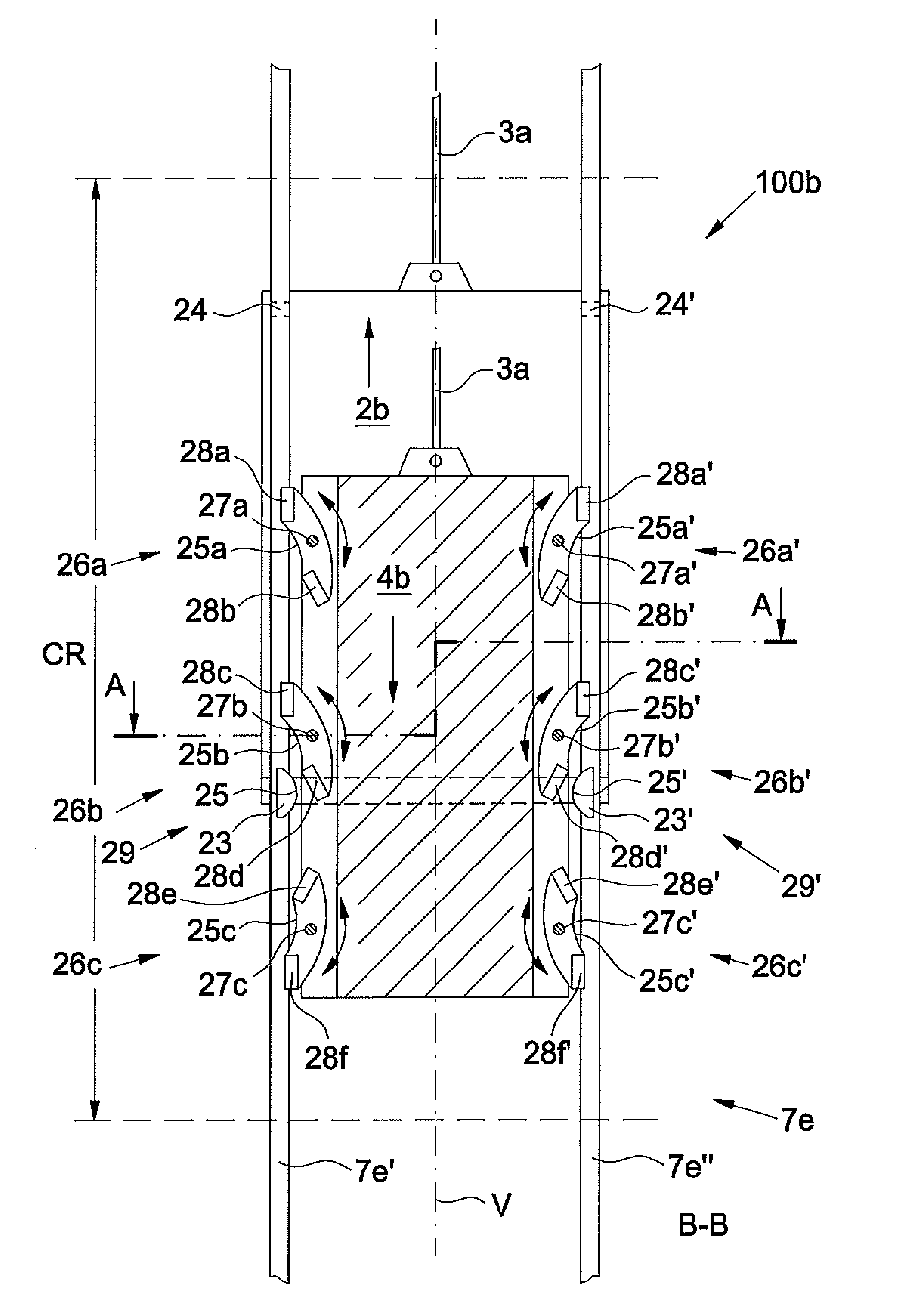
[0041]FIG. 3 shows an elevator system 100b according to the present technologies, in which an elevator car 2b and a counterweight 4b use a common pair of guide rails 7e, constituted of a first guide rail 7e′ and a second guide rail 7e″. The counterweight 4b and the elevator car 2b are supported by a suspending and driving means 3a. The elevator car 2b runs along the guide rail 7e′ with a guide shoe 23 and with a freely supported roller 24 and along the opposite guide rail 7e″ with a guide shoe 23′ and a freely supported roller 24′. The guide shoes 23 and 23′ define a contact surface 25 and 25′, respectively, capable of reciprocal contact with contact surfaces 25a-25c and 25a′-25c′ of switchable guiding elements 26a-26c and 26a′-26c′, respectively. Each of the guiding elements 26a-26c and 26a′-26c′ show an upper guide 28a, 28c, 28e, 28a′, 28c′, 28e′ and a corresponding lower guide 28b, 28d, 28f, 28b′, 28d′, 28f′, respectively. The guide shoe 23 of the elevator car 2b with its contact...

fourth embodiment

[0059]FIG. 6 shows an elevator system 100e according to the present technologies, with two deflecting elements 29e′ and 29f′ in the shape of a deflecting rail 37′ for a counterweight 4e. Both the counterweight 4e and an elevator car 2e are supported by a suspending and driving means 3d, whereas the elevator car 2e and the counterweight 4e share beyond a crossing region CR3 the same pair of guide rails 7h, of which the illustrated lateral and sectional view shows only a guide rail 7h″ laying in the back. The elevator car 2e is shown while running with guide shoes 23e′ and 23f′ along a guide rail 71″, which is within the crossing region CR3, as well as beyond it, straight. The counterweight 4e has several weight parts 40a-40d, linked possibly by pivotable jointed links 41a-41c, and is shown while entering the deflecting rail 37′. Each of the weight parts 40a-40d is guided by two guiding elements 39a′-39h′. Both the deflecting rail 37′ and the straight guide rails 7h″ and 71″ show guid...


PUM


Abstract

An elevator system has at least one common pair of guide rails for guide shoes of an elevator car, running along the common pair of guide rails, and for guiding elements of a counterweight, running along the same pair of guide rails. The guide shoes of the elevator car follow a straight trajectory and the guiding elements of the counterweight are deflectable by at least one deflecting element within a crossing region for the elevator car and the counterweight.

Description

CROSS-REFERENCE TO RELATED APPLICATION[0001]This application claims priority to European Patent Application No. EP10150366, filed Jan. 8, 2010, which is incorporated herein by reference.FIELD[0002]The present disclosure relates to an elevator system with an elevator car and a counterweight movable in opposite directions along an elevator shaft or hoistway. In particular, the present disclosure relates to the guide rails and the guide shoes of the elevator car and the guiding elements of the counterweight.BACKGROUND[0003]Elevator systems are normally equipped with a separate pair of guide rails mounted in the elevator shaft for each of the elevator car and the counterweight to guarantee the safe and independent run of the elevator car and the counterweight. The provision of two pairs of guide rails necessarily takes up considerable space within the cross-sectional area of the shaft which could otherwise be more usefully occupied by the elevator car. Furthermore, two pairs of guide ra...

Claims


Application Information

Patent Timeline
IPC IPC(8): B66B7/02B66B7/04
CPCB66B7/021B66B9/00B66B7/04
Inventor ROSSIGNOL, ERIC
Owner INVENTIO AG
Why Eureka
Try Eureka