Electronically controlled viscous fan drive with bushing

a technology of electric control and viscous fan, which is applied in the direction of fluid couplings, couplings, machines/engines, etc., can solve the problems of actuators being stuck, undesirable noise of the fan being driven, and the phenomenon of “morning sickness”

Active Publication Date: 2011-07-14
BORGWARNER INC
View PDF9 Cites 10 Cited by
  • Summary
  • Abstract
  • Description
  • Claims
  • Application Information

AI Technical Summary

Benefits of technology

[0011]The present invention overcomes potential problems with existing fluid coupling devices of the viscous shear type and provides an electronically controlled viscous fan drive system which prevents the system from undesirable lock-up in the “on” condition. The viscous clutch rotor is positioned inside the cover and body member which form an outer housing. A valve disk is attached to a shaft member which in turn is coupled to an actuating piston. The system is electronically controlled to allow fluid to pass from the reservoir chamber into the fluid operating chamber and activate the cooling fan as needed. The shaft and actuating piston are spring biased by a return spring such that the passageways between the fluid reservoir chamber and the fluid operating chamber are closed when the engine is turned off and no electrical activation is present.
[0012]In order to prevent the shaft and piston from being stuck in the “on” position and thus locking up the fan drive in the cooling condition, insulated washers and / or bushings are provided. The insulated members are non-conductive and prevent the electronic flux pattern from passing through them which could keep the shaft and piston from being returned to their rest position by the return spring.

Problems solved by technology

For some time, one of the problems associated with fluid coupling devices used to drive radiator cooling fans was the phenomenon known as “morning sickness”.
Such engaged operation often resulted in an undesirable noise of the fan being driven when it was not required.
One of the potential difficulties or concerns with some present fluid coupling devices of the viscous shear type is that the actuator could remain stuck in the engine “on”-electrically activated position, due to an improper flux pattern.
This could result in an overcooling situation and potentially create additional undesirable emissions from the vehicle engine.

Method used


Image

  • Electronically controlled viscous fan drive with bushing
  • Electronically controlled viscous fan drive with bushing
  • Electronically controlled viscous fan drive with bushing

Examples


Embodiment Construction

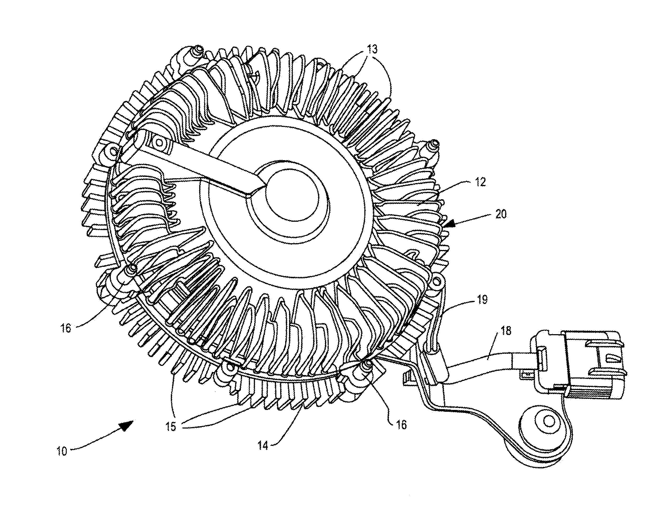
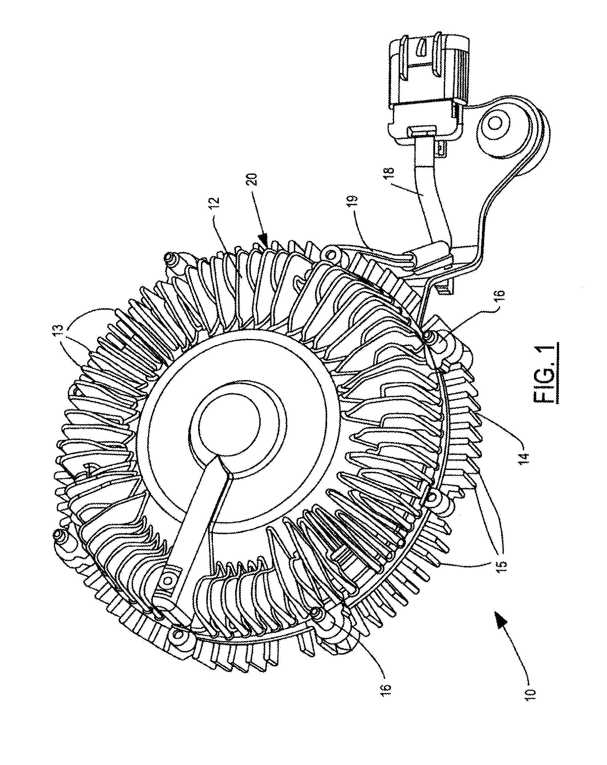
[0018]Referring now to the drawings, which are not intended to limit the invention, FIG. 1 illustrates a preferred form of a fluid coupling device 10 (“viscous fan drive”) of a type utilizing the present invention. The fluid coupling device 10 includes a cover member 12 and a body member 14, which are fastened together by bolts, washers, or other fastening means 16 in order to form a housing 20 with an internal cavity 22. The body and cover members can also be secured together by a rollover of the outer periphery of the cover member, as is well known in the art.

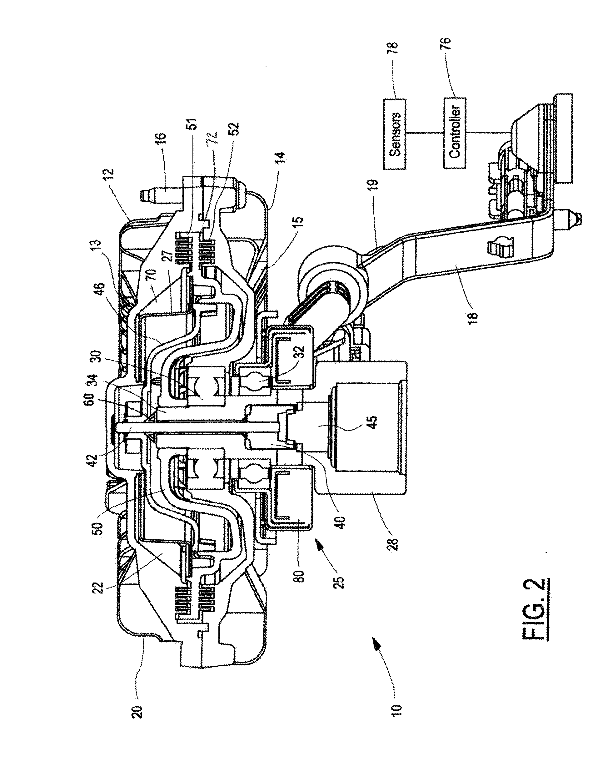
[0019]The fluid coupling device 10 is attached to a bracket member 18 which is used to mount the fluid coupling device to an engine or other portion of the vehicle or automobile where desired. Electric wire leads 19 are used to provide the electrical power to the actuator 25 in order to actuate it.

[0020]The fluid coupling device 10 is adapted to be driven by a liquid cooled engine and, in turn, to drive a radiator cooling fan...


PUM


Abstract

A viscous shear fan drive mechanism for a cooling fan. A moveable valve disk is provided which controls the quantity of fluid in the operating chamber. An electronic actuation system activates piston and shaft members which move the valve disk against the bias of a return spring to open the fill holes, allow fluid communication between the reservoir and working chambers, and allow rotation of the cooling fan. Without activation of the electronic actuation system, the flow of fluid to the working chamber is prevented. A non-magnetic or insulating bushing member adjacent the piston and shaft members prevents the system from sticking in the actuation condition when power is eliminated.

Description

CROSS REFERENCE TO RELATED APPLICATIONS[0001]This application claims priority to Application No. 61 / 052,643 filed on May 13, 2008, and entitled “Electronically Controlled Viscous Fan Drive With Bushing”, which is incorporated by reference herein.TECHNICAL FIELD[0002]The invention relates to fan drive systems and more specifically to electronically controlled viscous fan drive systems.BACKGROUND OF THE INVENTION[0003]The present invention relates to fluid coupling devices of the type including both fluid operating chambers and fluid reservoir chambers, and valving which controls the quantity of fluid in the operating chamber.[0004]Although the present invention may be used advantageously in fluid coupling devices having various configurations and applications, it is especially advantageous in a coupling device of the type used to drive a radiator cooling fan of an internal combustion engine, and will be described in connection therewith. It is to be understood, however, that the pres...

Claims


Application Information

Patent Timeline
Patent Type & Authority Applications(United States)
IPC IPC(8): F16D35/00
CPCF01P7/042F16D35/024F04D25/022
Inventor MAY, JAMES PATRICK
Owner BORGWARNER INC
Why Eureka
Try Eureka