
Novel RFID tag for use in dosimetry

Active Publication Date: 2011-07-14
LANDAUER INC
View PDF38 Cites 4 Cited by
  • Summary
  • Abstract
  • Description
  • Claims
  • Application Information

AI Technical Summary

Benefits of technology

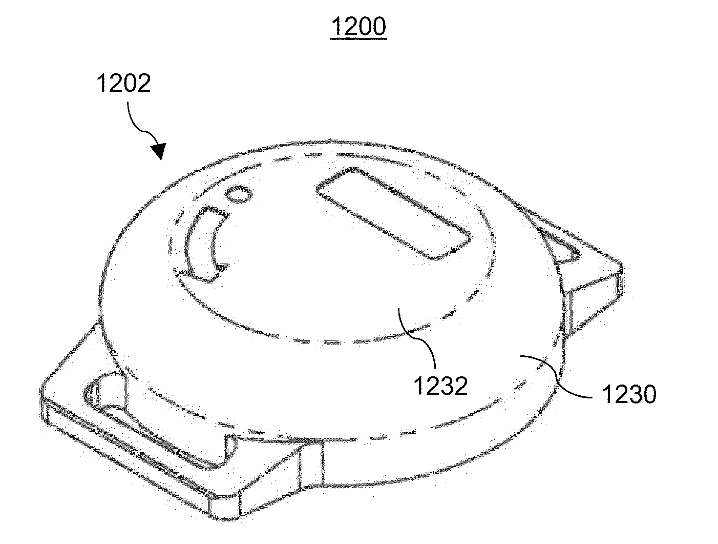
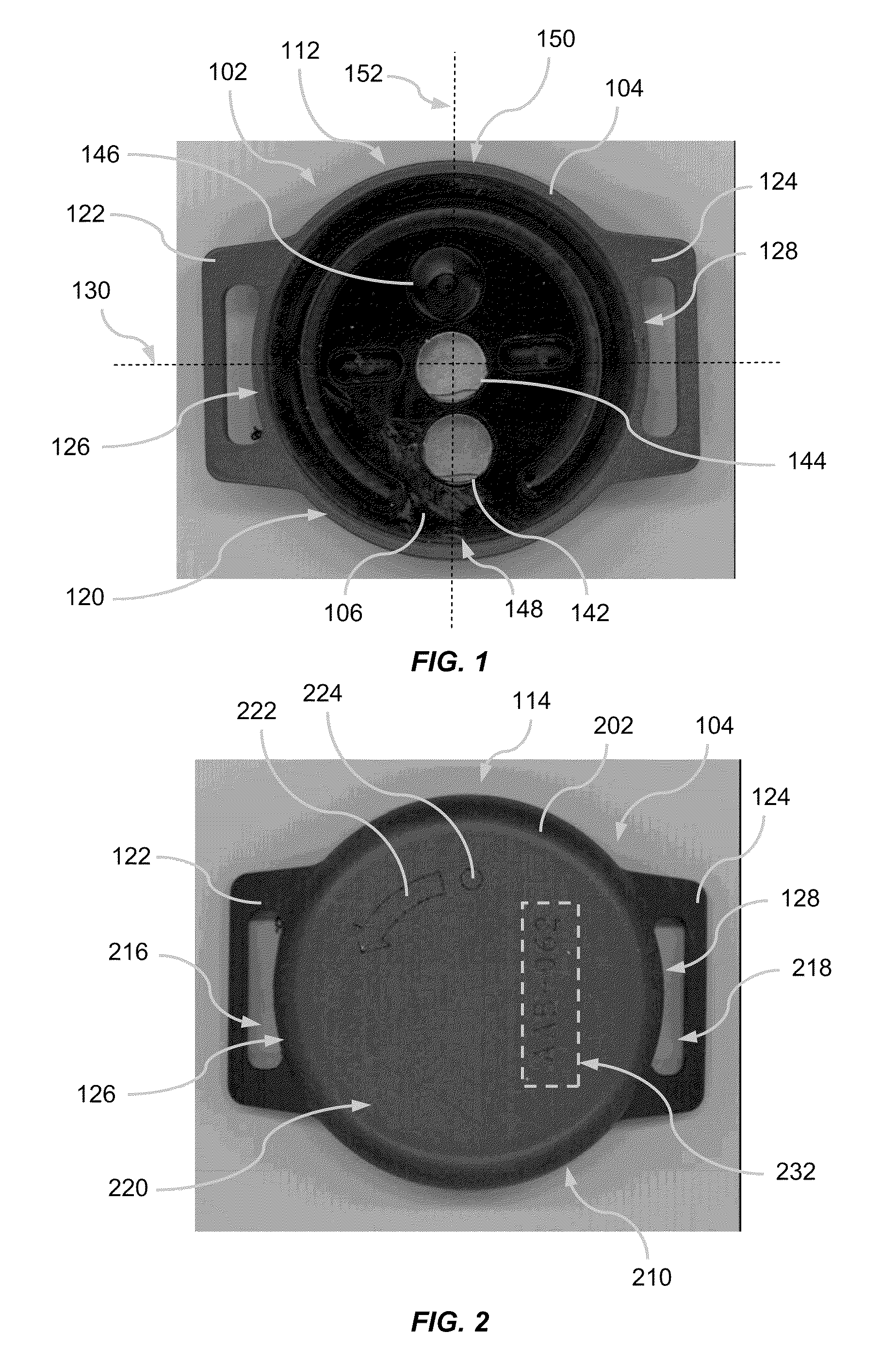
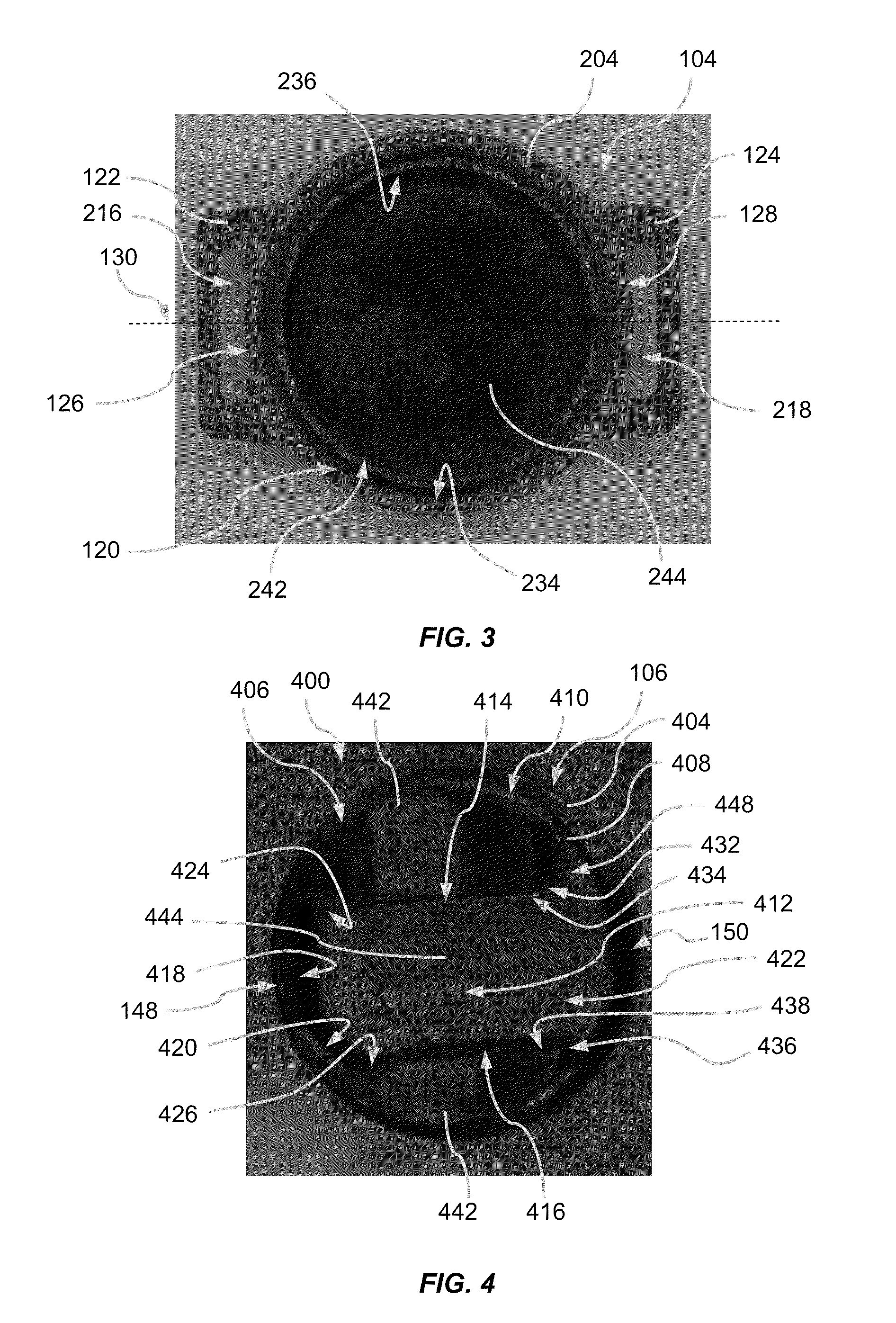
[0006]According to a broad aspect, the present invention provides a device comprising: a dosimeter sled comprising: one or more optically stimulated luminescence (OSL)

Problems solved by technology

A problem with existing systems for reading dosimeters is quickly accessing data necessary to perform a radiation dosage measurement for a specific individual.

Method used


Image

  • Novel RFID tag for use in dosimetry
  • Novel RFID tag for use in dosimetry
  • Novel RFID tag for use in dosimetry

Examples


example

Example

[0373]Dosimeter tests were conducted to determine the responses of three OSL sensors to radiation of different energies.

[0374]Groups of five dosimeters each were irradiated to a deep dose (defined as Hp10, or the dose occurring at a depth of 10 mm in tissue) of 500 mrem (5 mSv) from gamma or x-rays with mean energies of 53 keV, 73 keV, 118 keV, 162 keV and 662 keV. The dosimeters were mounted on a cylindrical phantom representing the wrist composed of polymethymethacrylate that is 7.3 cm in diameter and 45 cm tall. After exposure, the dosimeters were read out using a dosimeter reader of the type described above and shown in the drawings. FIG. 116 plots the mean luminescence in units of photon counts per mrem of delivered deep dose for each of the three OSL sensors in the dosimeter. The sensor labeled Al refers to the OSL sensor consisting of a single energy compensating cup composed of aluminum with a PTFE conversion filter between the OSLM and the aluminum cup. Likewise, the...


PUM


Abstract

Described is a dosimeter sled comprising: one or more optically stimulated luminescence (OSL) sensors mounted in the dosimeter sled and an RFID tag comprising an antenna for communicating with an RFID tag reader and a non-volatile memory for storing data therein.

Description

CROSS-REFERENCE TO RELATED APPLICATIONS[0001]This application claims benefit of priority to U.S. Provisional Patent Application No. 61 / 294,142 to Yoder, entitled RADIATION DOSIMETER AND RADIATION READER, filed Jan. 12, 2010, which is incorporated herein by reference in its entirety. This application also makes reference to the following U.S. Patent Applications: U.S. patent application Ser. No. ______ filed ______, entitled PORTABLE DOSIMETER; U.S. patent application Ser. No. ______ filed ______, entitled NOVEL FILTERS FOR USE IN DOSIMETRY; U.S. patent application Ser. No. ______ filed ______, entitled DOSIMETER SLED; U.S. patent application Ser. No. ______ filed ______, entitled PORTABLE READER FOR A DOSIMETER; U.S. patent application Ser. No. ______ filed ______, entitled DATA STORAGE MECHANISM AND COMMUNICATION MECHANISM FOR PORTABLE DOSIMETER; U.S. patent application Ser. No. ______ filed ______, entitled READING MECHANISM FOR DOSIMETER; U.S. patent application Ser. No. ______ f...

Claims


Application Information

Patent Timeline
IPC IPC(8): G06K19/077
CPCG01T3/00G01T1/105G01T1/02G01T1/10G06K19/07G06K17/00
Inventor YODER, R. CRAIG
Owner LANDAUER INC
Learn More