Unlock instant, AI-driven research and patent intelligence for your innovation.

Static line piggyback parachute system

a parachute system and static line technology, applied in parachutes, emergency equipment, transportation and packaging, etc., can solve the problems of limited vision of parachutists in that area, difficult deployment of front mounted reserve parachutes, and more difficult to see forward and below

Inactive Publication Date: 2011-07-14
STRONG EDWARD
View PDF8 Cites 13 Cited by
  • Summary
  • Abstract
  • Description
  • Claims
  • Application Information

AI Technical Summary

Problems solved by technology

However, this configuration has several drawbacks.
For instance, a bulky reserve parachute container so located is in front of and below a parachutist's eyes and therefore limits the parachutist's vision in that area.
Additionally, front mounted reserve parachutes are difficult to deploy, and often static-line jumps of this nature are conducted under particularly unforgiving low-altitudes.
This awkwardly leans the parachutist back once under an inflated reserve canopy, which makes it more difficult to see forward and below, and presents further opportunity for back and / or neck injury during deployment and landing.
However, a parachuting system configured for sport or tandem parachuting is not suitable for use during parachuting operations when the parachutist's body is parallel to the line of deployment during deployment.
As a result, the deployment path of the main parachute would be blocked by the reserve container.
At the very least this would cost valuable time.
It could also push the reserve container forward and out of the way and into the parachutist's head, which may injure the parachutist and / or cause the parachutist to begin a forward roll during the deployment of the main parachute, which is an unwanted condition.
At worst the main parachute may not deploy.
A sport or tandem container configuration is further unsuitable for deployment when parallel to the line of deployment because once the main parachute has deployed, the reserve parachute would remain on the parachutist's back slightly below the parachutist's neck.
As a result the parachutist may land rolling backwards, and the hard reserve container on the back of a parachutist that is landing backwards may hit the parachutist in the head causing injury, or may cause neck strain as the parachutist's roll is suddenly interrupted by the reserve container.
In addition, many sport and tandem reserve parachute activation systems require a greater amount of time and altitude to develop a fully inflated reserve parachute than may be available in parachuting operations when the parachutist is parallel to the line of deployment.

Method used


Image

  • Static line piggyback parachute system
  • Static line piggyback parachute system
  • Static line piggyback parachute system

Examples


Embodiment Construction

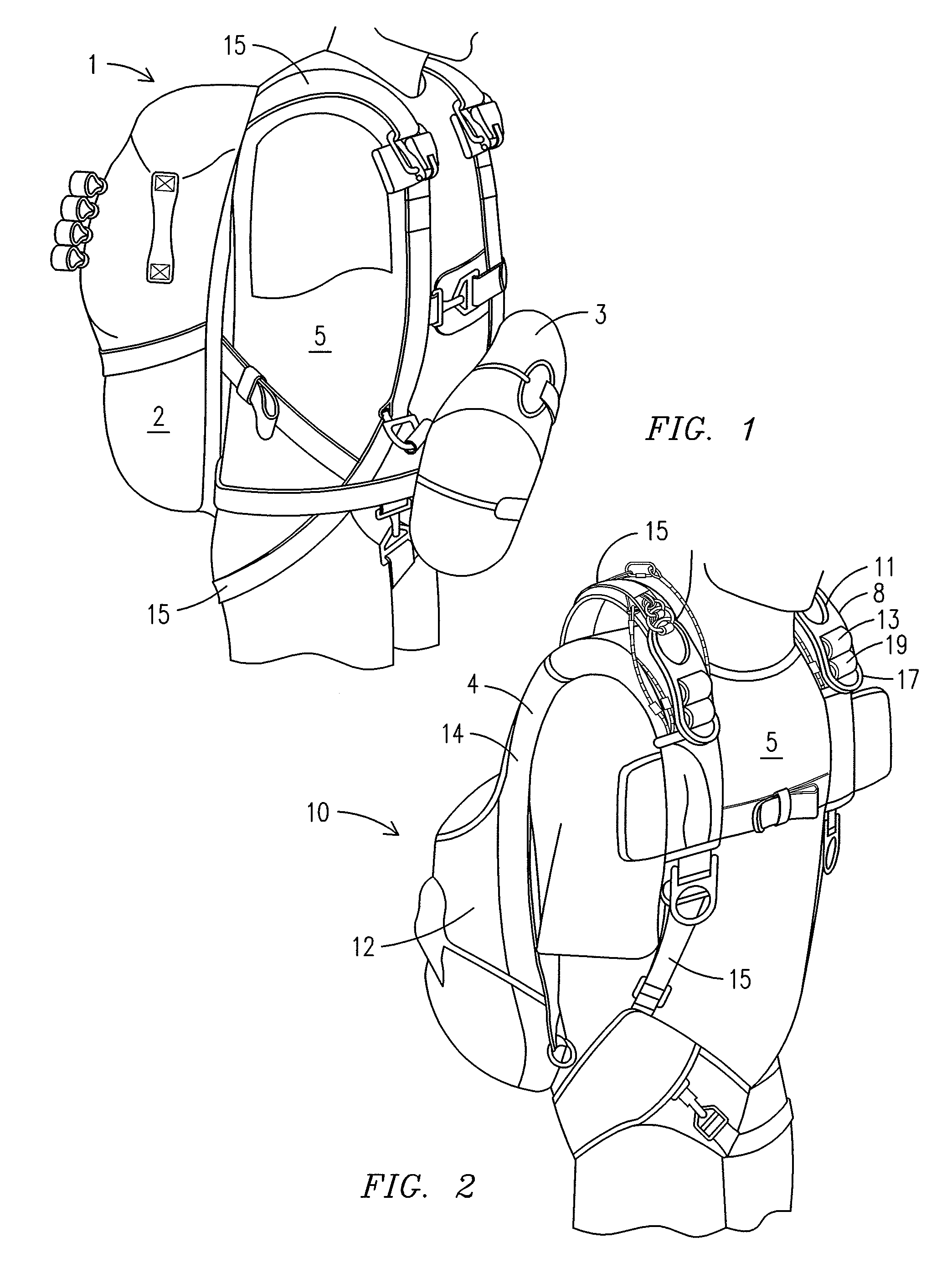
[0025]The inventor of this innovative parachute system has created a parachute system for use in parachute operations where the parachutist is parallel to the line of deployment when the main parachute is deployed (i.e., “static-line” jumping), that positions both the main parachute and the reserve parachute on the back of the parachutist. By moving the reserve parachute from in front of the parachutist to behind the parachutist, between the main parachute and the parachutist, the inventor has created a system that overcomes many of the disadvantages of the prior art. While doing this the inventor has further created some advantages never before available in a parachute system.

[0026]Positioning the reserve container between the main container and the parachutist, such that it does not over-hang the main parachute container when the parachutist is vertically oriented, (i.e., during deployment of the main parachute), permits the innovative parachute system to utilize the basic princip...


PUM


Abstract

A parachute container system including: a reserve compartment; a main compartment; a reserve parachute pathway configured to enable a mechanical connection between a reserve parachute canopy and a reserve parachute connection point external to the parachute container system when a reserve parachute canopy is positioned in the reserve compartment; and a main parachute pathway configured to enable a mechanical connection between a main parachute canopy and a main parachute connection point external to the parachute container system when a main parachute canopy is positioned in the main compartment. When the parachute container system is positioned on a parachutist at least a portion of the reserve compartment is disposed between the main compartment and the parachutist.

Description

FIELD OF THE INVENTION[0001]This invention relates to parachute systems. Particularly, this invention relates to an improved parachute system for parachute jumping when the parachutist may be oriented parallel to a line of deployment of the main parachute, such as static-line jumping.BACKGROUND OF THE INVENTION[0002]Static-line parachute jumping is one form of parachute jumping where the parachutist may be oriented parallel to a line of a deploying main parachute. In conventional static-line parachute jump operations a parachutist wears a harness that holds a main parachute container on the parachutists back. The main parachute container houses a main parachute retained inside a main parachute deployment-bag. A separate reserve container is attached to the harness on the front side of the parachutist. A tether known as a static-line is attached to the aircraft at a first end. Near the second end the static-line is attached to a mechanism that will open the main parachute container. ...

Claims


Application Information

Patent Timeline
IPC IPC(8): B64D17/62B64D17/50B64D17/30B64D17/64B64D17/40
CPCB64D17/30B64D17/64B64D17/50
Inventor STRONG, EDWARD
Owner STRONG EDWARD