Super light-field lens

a super light-field, lens technology, applied in the field of optical systems, can solve the problems of not being used, limiting the use of prior systems, and not providing 3 or 4 mm clearan

Active Publication Date: 2011-07-14
PIXAR ANIMATION
View PDF6 Cites 138 Cited by
  • Summary
  • Abstract
  • Description
  • Claims
  • Application Information

AI Technical Summary

Problems solved by technology

Hence, prior systems were constrained as they could not be used with cameras which typically require a minimum lens clearance of about 30 to 40 mm, which far exceeds the 3 or 4 mm clearance provided by the lenslet array.
Further, adapting cameras to work with such a plenoptic imaging system can be a costly and onerous solution.

Method used


Image

  • Super light-field lens
  • Super light-field lens
  • Super light-field lens

Examples


Embodiment Construction

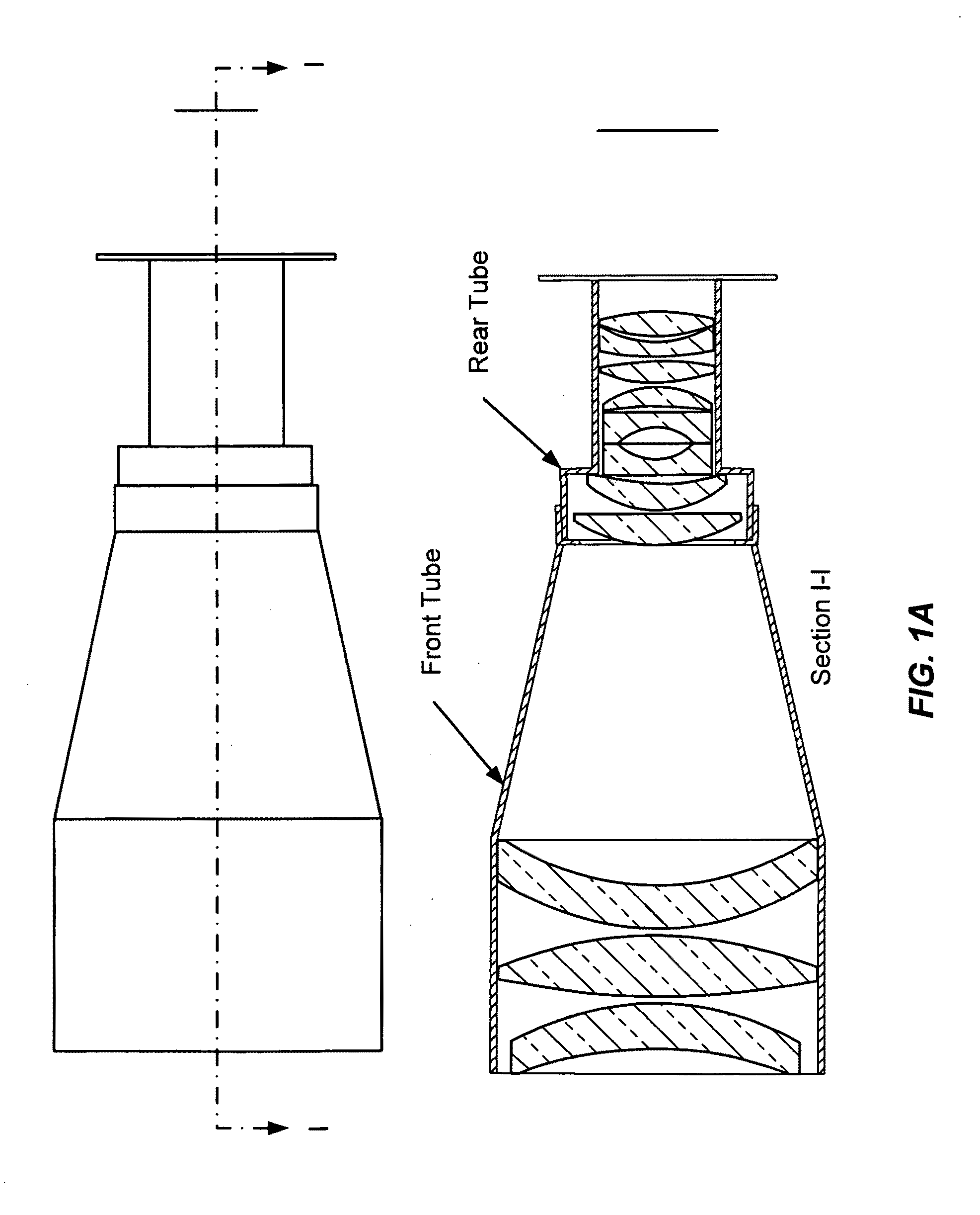
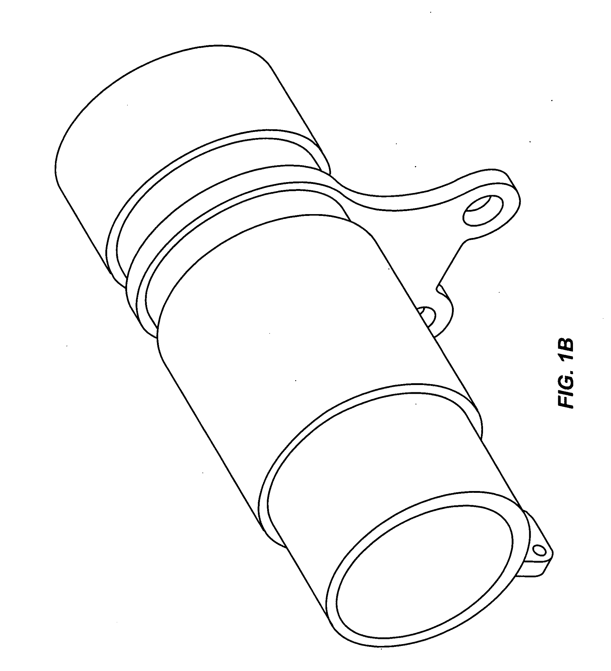
[0030]FIGS. 1a and 1b illustrate a relay element according to one embodiment. As shown in FIG. 1a, a first set of optical elements in the front tube (field lens such as a prime lens) receives light refracted by the lenslet array (not shown) and collimates and focuses that light onto a second set of optical elements in the rear tube, which focus the light onto an image plane (not shown). A sensor, e.g., CCD, CMOS or film, positioned at the image plane receives and records image(s). FIG. 1b shows a perspective view of an example of a housing structure (e.g., lens barrel), with the relay lens on the left side

[0031]In certain aspects, the field lens, lenslet array and relay optical elements are contained within a housing structure (e.g., lens barrel) that allows for adaption of distance between the various elements, e.g., by manual rotation or manipulation, or by electronic control via a controller subsystem. FIG. 2 is a side view of a more detailed example of a housing structure (e.g.,...


PUM


Abstract

Light field imaging systems, and in particular light field lenses that can be mated with a variety of conventional cameras (e.g., digital or photographic / film, image and video / movie cameras) to create light field imaging systems. Light field data collected by these light field imaging systems can then be used to produce 2D images, right eye / left eye 3D images, to refocus foreground images and / or background images together or separately (depth of field adjustments), and to move the camera angle, as well as to render and manipulate images using a computer graphics rendering engine and compositing tools.

Description

CROSS-REFERENCES TO RELATED APPLICATIONS[0001]This application claims the benefit of U.S. Provisional Application Ser. No. 61 / 252,996, filed Oct. 19, 2009, entitled “Super Light Field Lens,” which is hereby incorporated by reference in its entirety for all purposes.BACKGROUND[0002]The present invention relates generally to optical systems, and more particularly to light field imaging systems or plenoptic imaging systems.[0003]In prior light field gathering, or plenoptic imaging systems, a prime lens typically focuses light onto a lenslet array positioned close to the focal plane of the prime lens. The lenslet array includes a plurality of microlenses that each refracts light to thereby form a plurality of microlens images that are collected by a sensor located proximal the focal plane of the microlenses. Typically this distance to the sensor is on the order of a couple to a few millimeters (mm) from the lenslet array as determined by the aperture and f# of the microlenses. Hence, pr...

Claims


Application Information

Patent Timeline
Patent Type & Authority Applications(United States)
IPC IPC(8): H04N5/232G02B27/12H04N5/225
CPCG02B13/16H04N13/0207H04N5/232H04N5/2254H04N13/207H04N23/957
Inventor DIFRANCESCO, DAVIDSELKIRK DUFF, THOMAS DOUGLASVANDEWETTERING, MARKFLOWERS, PETER
Owner PIXAR ANIMATION
Why Eureka
Try Eureka