Gaze Point Tracking Using Polarized Light

a technology of polarized light and point tracking, applied in the field of polarized light, can solve problems such as excessive brightness, and achieve the effects of preventing overexposure, accurate determination of center and centroids, and stable and accurate determination of user's gaze targ

Inactive Publication Date: 2011-07-14
WORDS
View PDF4 Cites 53 Cited by
  • Summary
  • Abstract
  • Description
  • Claims
  • Application Information

AI Technical Summary

Benefits of technology

[0006]In the present invention, the pupil and glint are imaged in a manner that allows their exposures to be independently optimized. Advantage is taken of two facts, first the fact that the glint is revealed by reflected light, whereas the pupil and iris are revealed by scattered light, and second, the fact that reflected light preserves polarization whereas scattered light does not. Since the glint is brighter than the iris, and is revealed by polarized light, it can be selectively attenuated as much as desired, and overexposure prevented. Accordingly, higher quality images of the pupil and glint can be captured, allowing for a more accurate determination of their center and centroids, and consequentially a more stable and accurate determination of the user's gaze target.

Problems solved by technology

Alternatively, the glint (or glints) in the image may be caused by the pupil illuminator, except that its otherwise excessive brightness is attenuated by adjusting the camera polarizer to substantially but not complete extinguish the glint.

Method used


Image

  • Gaze Point Tracking Using Polarized Light
  • Gaze Point Tracking Using Polarized Light
  • Gaze Point Tracking Using Polarized Light

Examples


Embodiment Construction

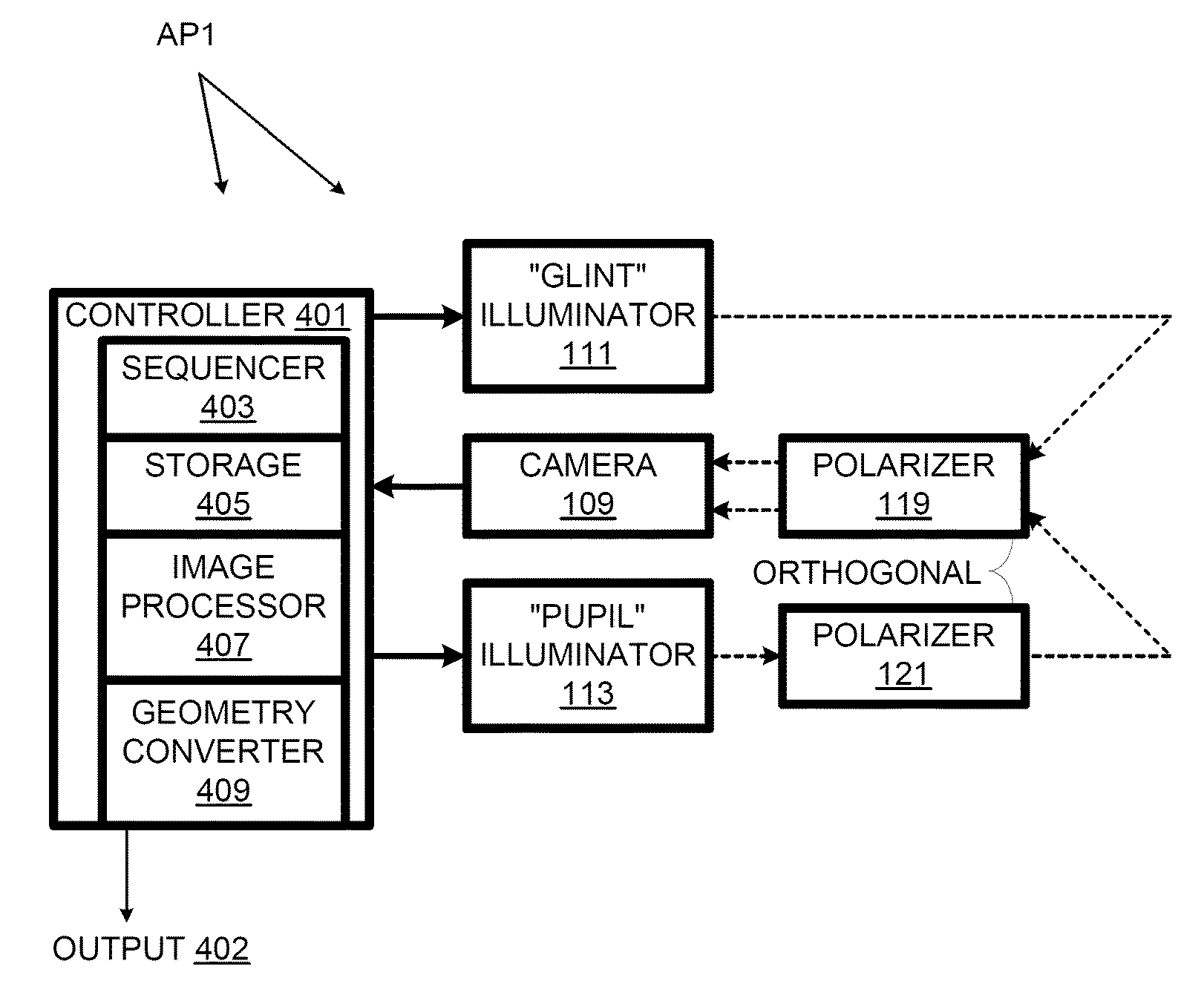
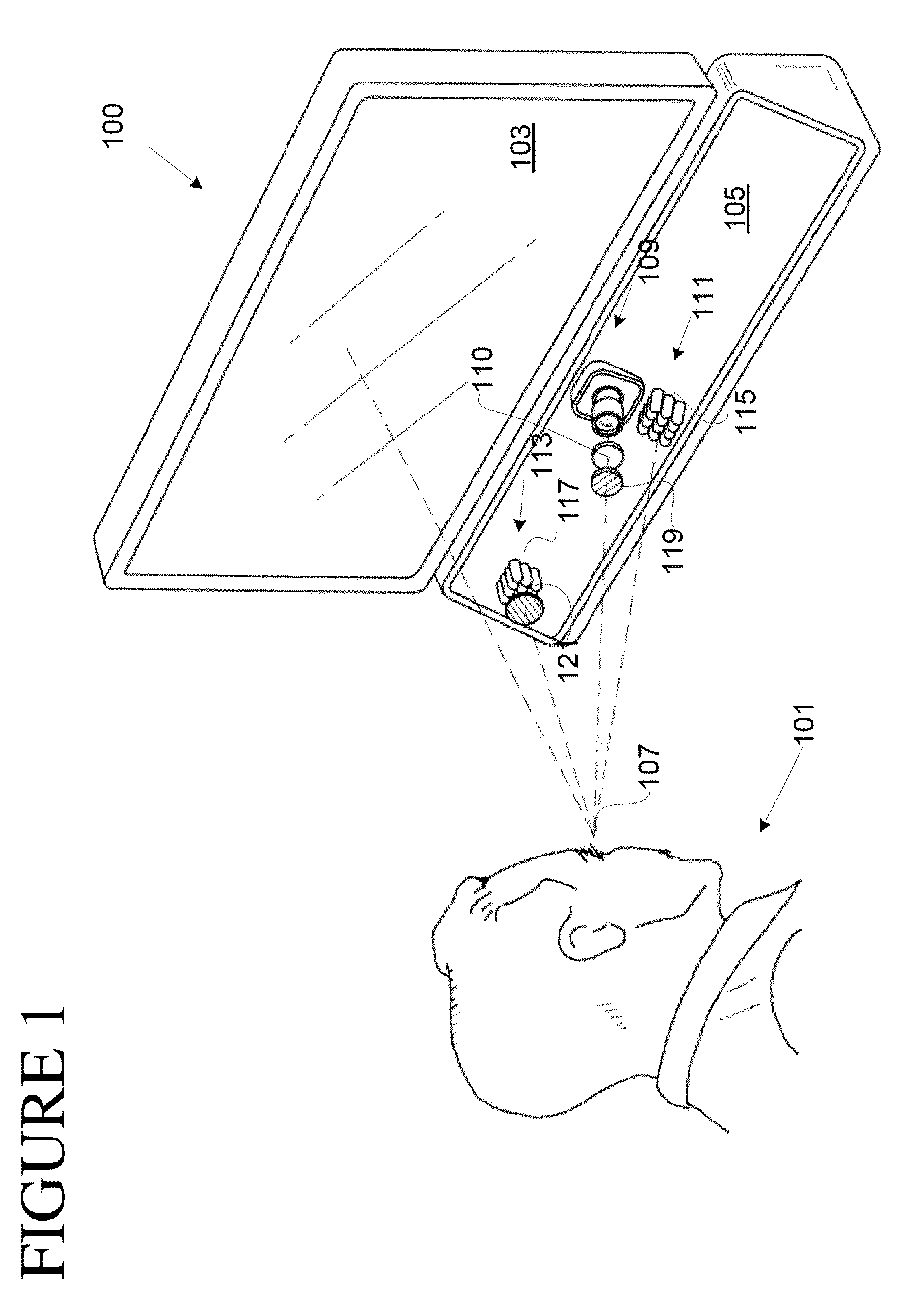
[0019]FIG. 1 is a view of a user 101 interacting with a computer system 100 according to one embodiment of the current invention. System 100 includes a display 103 and a gaze-tracking system 105 for tracking the motion of user eye 107. Gaze-tracking system 105 includes a camera 109, a “glint” illuminator 111, and a “pupil” illuminator 113. Illuminators 111 and 113 include respective LED arrays 115 and 117, which both emit infra-red light invisible to eye 107 but detectable by camera 109. Illuminator 113 is sufficiently bright that it can overcome ambient light.

[0020]Camera 109 includes a near infra-red (NIR) filter 110 to block visible light, diminishing interference in the camera images from ambient sources of light. LED arrays 115 and 117 illuminate the eye from below with NIR light. In alternative embodiments, visible light is used to illuminate, the illuminators are not below eye level, and exposures are varied in the camera.

[0021]Camera 109 includes a polarizing filter 119 moun...


PUM


Abstract

A process and a system that determine a glint position and a pupil position are disclosed. The process includes illuminating one eye to produce a glint on that eye, and obtaining a glint image of that eye showing that glint on that eye. A glint position is determined at least in part from that glint image. The process further includes illuminating that eye using polarized light, and obtaining, through a polarizer that can attenuate reflected polarized light, a pupil image of that eye. A pupil position is determined at least in part from that pupil image.

Description

RELATED APPLICATION[0001]The present application is a continuation-in-part of U.S. application Ser. No. 12 / 684,613, filed on Jan. 8, 2010, pending, titled “Gaze Tracking Using Polarized Light”, which is incorporated herein by reference in its entirety, and to which application we claim priority under 35 USC §120.BACKGROUND[0002]A number of techniques for determining a viewer's gaze point by using eye tracking have been disclosed in the prior art. Some of them allow a person to control aspects of their environment by using eye movement. For example, a quadriplegic might use such a system for controlling his or her computer or other device to facilitate reading, communicating, and performing other useful tasks.[0003]One class of gaze-tracking techniques uses artificial illumination to produce a glint reflection in the cornea of an eye. A camera captures an image of the eye, and in the image the relative positions of the centers of the pupil and glint are measured, as being indicative ...

Claims


Application Information

Patent Timeline
Patent Type & Authority Applications(United States)
IPC IPC(8): A61B3/14
CPCG06F3/013A61B3/113G06V40/19
Inventor GORDON, GARY B.
Owner WORDS
Why Eureka
Try Eureka