
Hole cutter with extruded cap

a cutter and extruder technology, applied in manufacturing tools, forging/pressing/hammering apparatus, transportation and packaging, etc., can solve the problems of high material cost of thick plate material, high cost of machining process for forming recesses and arbors and driving holes, and relatively time-consuming machining process. , to achieve the effect of significant strength improvemen

Active Publication Date: 2011-07-14
BLACK & DECKER INC
View PDF26 Cites 48 Cited by
  • Summary
  • Abstract
  • Description
  • Claims
  • Application Information

AI Technical Summary

Benefits of technology

The invention is a cap that is made by extruding a hub and then adding a plate to the outside of the hub. The cap has a plate thickness of at least 0.134 inches outside the hub but inside the "B" diameter. This design provides significant strength improvements over traditional drawn sheet metal caps, without adding extra thickness to the plate.

Problems solved by technology

The technical problem addressed in this patent text relates to improving the design of hole cutters while reducing materials usage and manufacturing costs without compromising their structural integrity and performance.

Method used


Image

  • Hole cutter with extruded cap
  • Hole cutter with extruded cap
  • Hole cutter with extruded cap

Examples


Embodiment Construction

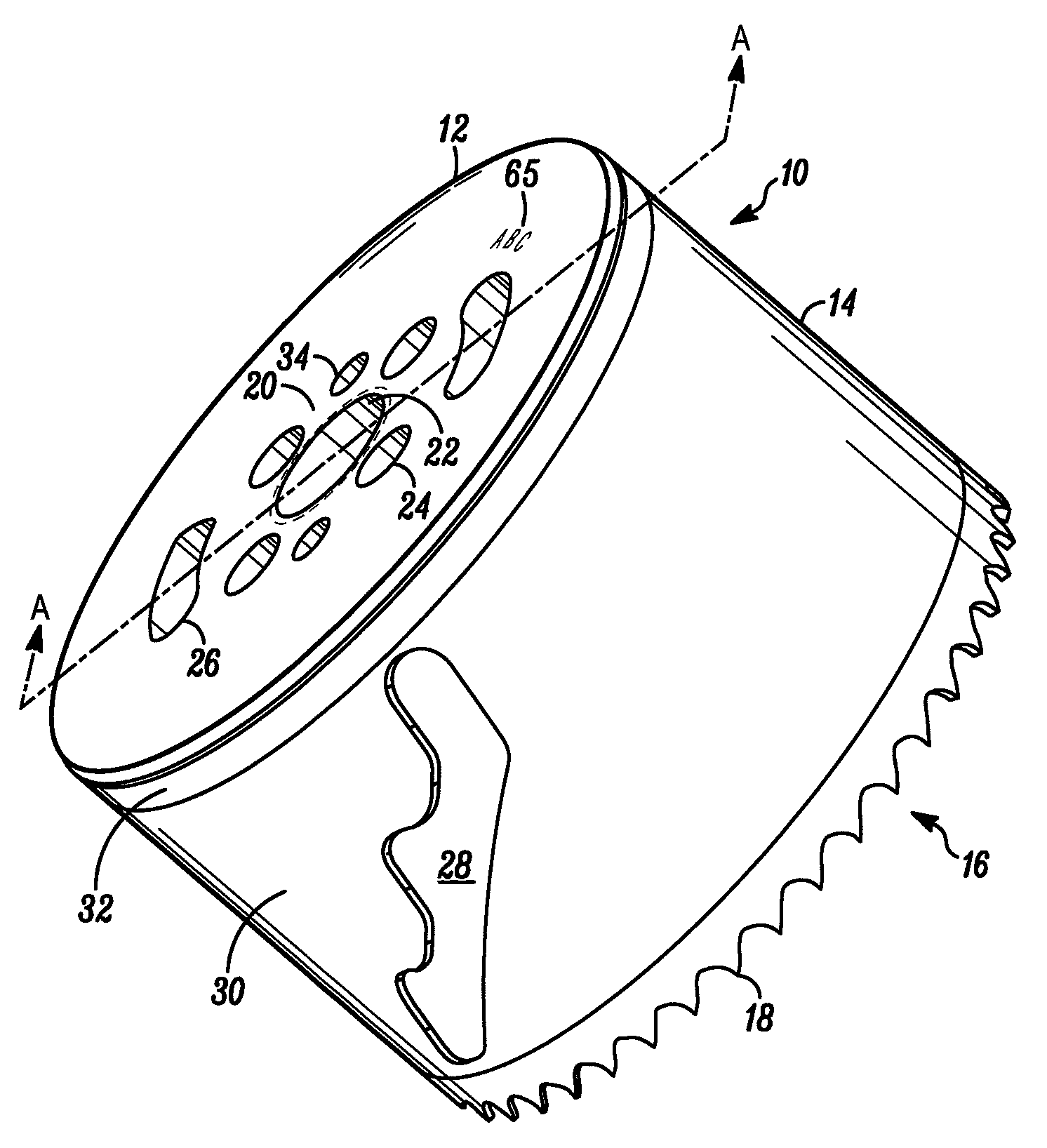
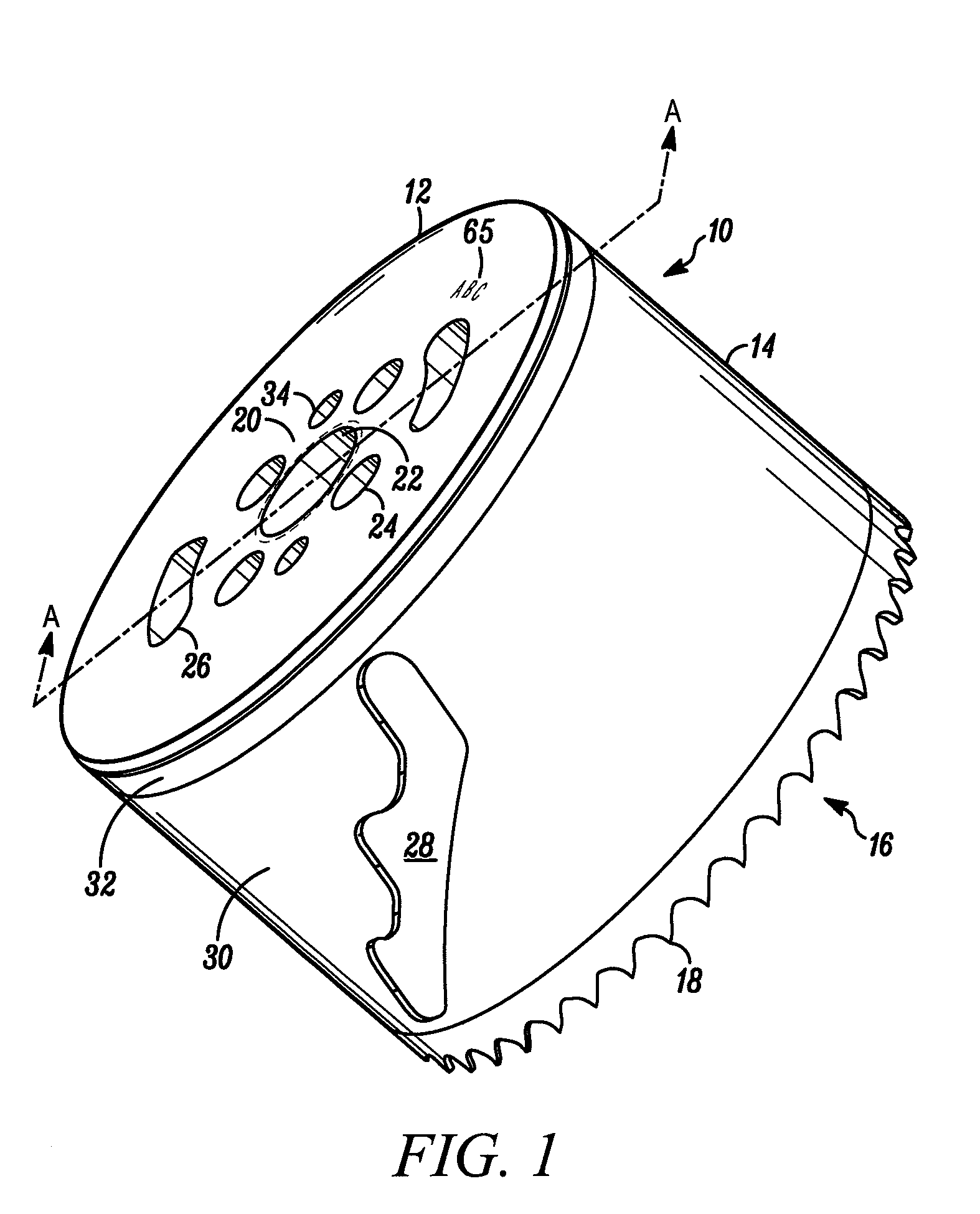
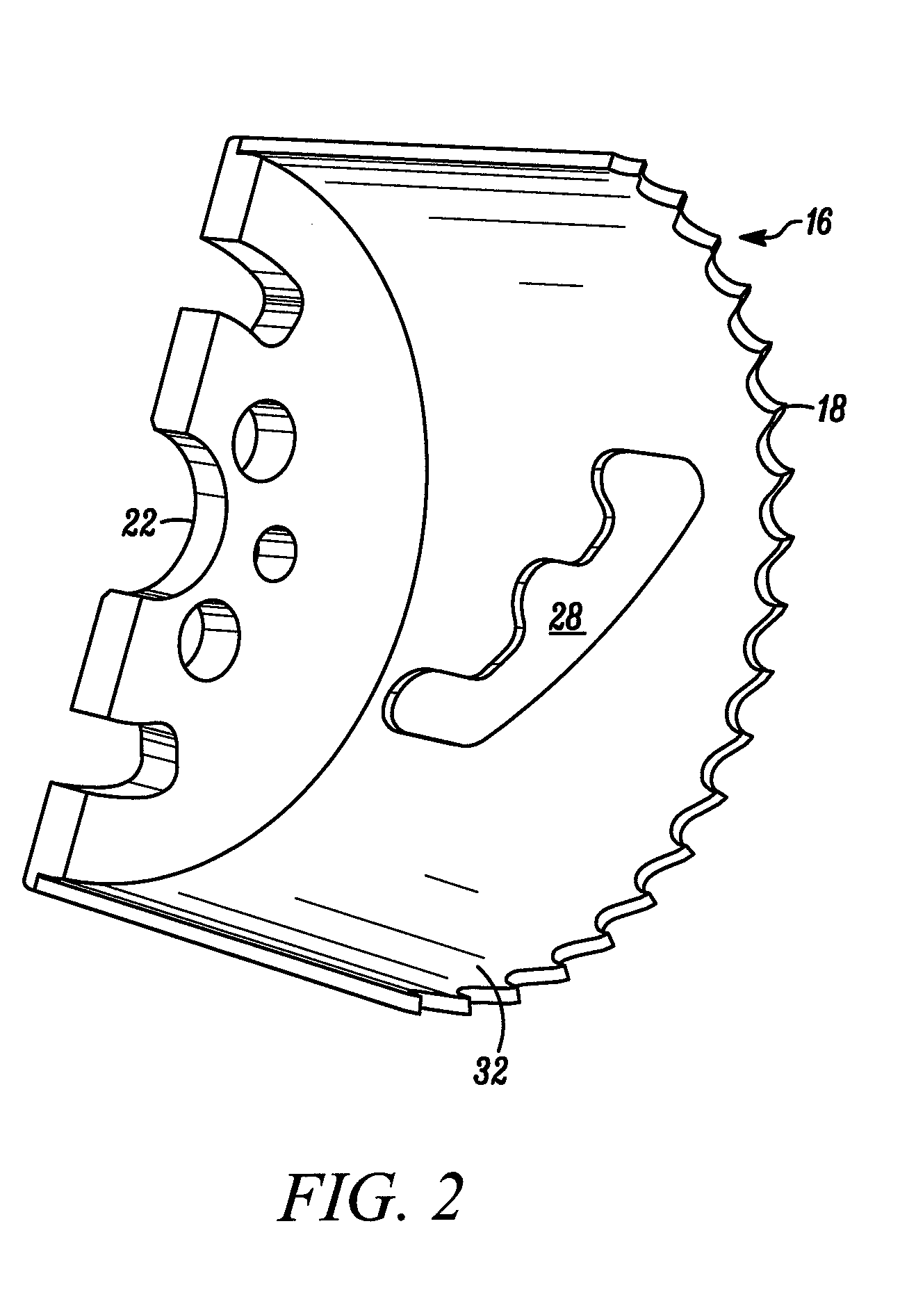
[0033]In FIGS. 1 and 2, a hole cutter embodying the present invention is indicated generally by the reference numeral 10. The term “hole cutter” is used herein to mean a tool that cuts holes in work pieces, such as wood, metal or other work pieces, and includes without limitation hole saws. The hole cutter 10 includes a cap 12 and a cylindrical or annular blade body 14 extending axially from the cap. The blade body 14 is fixedly secured, such as by welding, to the cap 12.

[0034]The blade body 14 has a cutting edge 16 at its distal end opposite the cap 12 and a plurality of cutting teeth 18. The cutting teeth 18 are configured to cut into a work piece when the cutter 10 is applied to a work piece and rotated about the axis of rotation Y in a cutting direction. Presently preferred configurations of the cutting edge and cutting teeth are provided in the following co-pending patent applications assigned to the assignee of the present invention and are hereby expressly incorporated by ref...


PUM

PropertyMeasurementUnit
Angleaaaaaaaaaa
Lengthaaaaaaaaaa
Thicknessaaaaaaaaaa

Abstract

A hole cutter having an extruded plate cap and methods and apparatuses for making such caps and hole cutters. The plate cap has planar opposing external and internal surfaces with an extruded hub extending axially inwardly from the internal surface. An aperture extends axially through the hub from the external surface. At least a portion of the aperture can be threaded for threaded engagement with a driving arbor. The hub is long enough so that the threaded portion contains at least two full threads. A blade body with a cutting edge is attached to the cap to form a hole cutter.

Description


Claims


Application Information

Patent Timeline
Owner BLACK & DECKER INC
Features
  • Generate Ideas
  • Intellectual Property
  • Life Sciences
  • Materials
  • Tech Scout
  • Unparalleled Data Quality
  • Higher Quality Content
  • 60% Fewer Hallucinations
Learn More