Supercharge Your Innovation With Domain-Expert AI Agents!

Paper binding assembly

a technology of paper clips and assembly, applied in the field of paper clips, can solve the problems of easy dislocation, high probability, and inability to keep the group of papers aligned, and achieve the effect of facilitating their suspension

Inactive Publication Date: 2011-07-21
MADER MARK E +2
View PDF20 Cites 0 Cited by
  • Summary
  • Abstract
  • Description
  • Claims
  • Application Information

AI Technical Summary

Benefits of technology

"The present invention provides a binding assembly for securing loose sheets of paper together in a unitary fashion and facilitating their hanging on a bulletin board or the like. The assembly includes a paper clip made of a metallic body that can be bent and formed into a squared or rounded shape. The clip has guide legs that are bent over against the back surface of the paper to hold the sheets together. The clip also has an opening that creates a tab for hanging. The invention is an attractive addition to any paper and can include personalization or advertizing indicia. Overall, the invention provides a secure and organized way to bind and display multiple sheets of paper."

Problems solved by technology

While paper clips operate generally well, they have drawbacks.
For example, paper clips do not have the capability of keeping the group of papers aligned evenly along the top and side surfaces, as the securing mechanism does not have structured means to provide such alignment.
Further, they can easily be dislodged as the stack of paper is moved or handled.
Still further, if the paper clip is used to suspend the paper, it is highly likely that the papers will slide out and fall therefrom.
However, this particular type of arrangement has the undesirable feature of mutilating the sheets of paper, which is not particularly attractive when used in conjunction with business letters or legal documents.
Further, such binding tends to be relatively permanent, in that the papers cannot be easily separated.
A staple, however, is not a particularly attractive paper fastener.
Also the staple utilizes the undesirable feature of puncturing the sheets of paper forming holes.
While staples can hold a stack of paper in a previously established alignment, removing a staple is often problematic.
Once removed, the staple leaves holes in the paper and often creates tears in the paper during removal.

Method used


Image

  • Paper binding assembly
  • Paper binding assembly
  • Paper binding assembly

Examples


Embodiment Construction

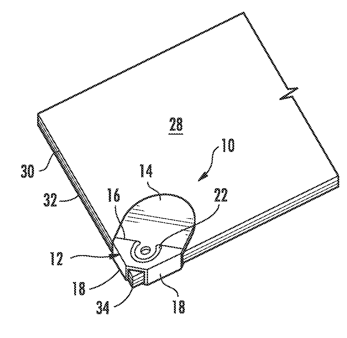
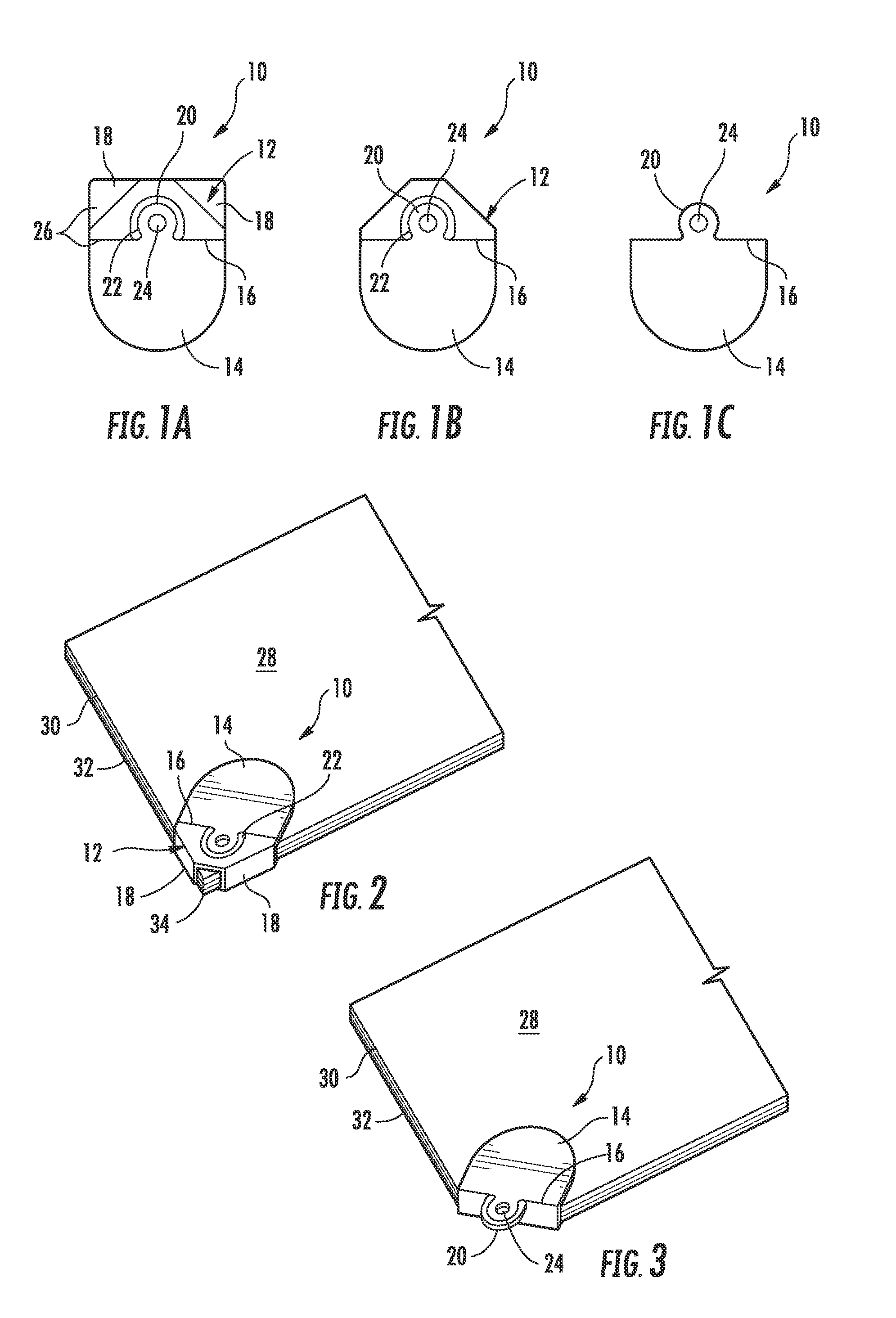
[0018]Now referring to the drawings, the paper binding clip of the present invention is shown and generally illustrated in the figures. As can best be seen at FIG. 1, the present invention is most generally directed to a paper binding clip 10 for binding a corner of a stack that contains a plurality of sheets of paper, such that the stack of paper has at least a front sheet and a rear sheet and preferably additional sheets positioned therebetween. The paper binder clip 10 has a body that includes a top portion 12, a bottom portion 14 and a fold line 16 between the top 12 and bottom 14 portions. Guide legs 18 extending from the top portion 12 of the body that are bent rearwardly adjacent the stack of paper as will be described in more detail below and the top portion 12 is bent rearwardly relative to the bottom portion 14 along the fold line 16 thereby trapping and folding the corner of the stack of paper against the bottom of the rear sheet binding the stack therein. A tab 20 extend...


PUM


Abstract

A binding assembly is provided that is applied to the corner of a plurality of loose sheets of paper to secure them in a unitary fashion and facilitates their being hung on a bulletin board or the like. The paper binder clip is constructed of a sheet material metallic body capable of being bent and when bent will remain in the bent position. The binder clip body is placed against sheets of paper that are to be secured together, the corners are bent over the edges of the paper and the body is bent in a manner that also folds over the paper corners. When the paper is received in the binder clip a tab remains straight and extends outwardly from the binder clip. The tab preferably includes a hole therein that facilitates hanging of the binder clip and the sheets of paper secured therein.

Description

BACKGROUND OF THE INVENTION[0001]The present invention relates generally to a binding assembly that secures a plurality of loose sheets of paper to one another and allows them to be suspended therefrom. More specifically, the present invention provides for a binding assembly that is applied to the corner of a plurality of sheets of paper in a manner that holds the papers together in a unitary fashion and facilitates their being hung on a bulletin board or the like.[0002]The use of paper clips or paper fasteners has long been known. A typical prior art paper clip is made of wire that is bent to form two or more adjacent loops wherein a plurality of sheets of paper are positioned between the loops of the wire clip thereby binding the sheets of paper together. Paper clips, in all their varied forms, function to hold individual papers together as a temporary attachment device that can be readily removed. While paper clips operate generally well, they have drawbacks. For example, paper c...

Claims


Application Information

Patent Timeline
Patent Type & Authority Applications(United States)
IPC IPC(8): B42F1/12B42F1/04B42F1/08G09F3/00
CPCB42F1/12Y10T24/208G09F3/16
Inventor MADER, MARK E.IANNUCCI, JR., FRANK H.IANNONE, JR., EDWARD
Owner MADER MARK E
Features
  • R&D
  • Intellectual Property
  • Life Sciences
  • Materials
  • Tech Scout
  • Unparalleled Data Quality
  • Higher Quality Content
  • 60% Fewer Hallucinations
Learn More