Automatic document conveying device and image forming apparatus including the same

a document conveying device and document technology, applied in the direction of electrical apparatus, pictoral communication, thin material processing, etc., can solve the problems of increasing production cost, space required for setting respective drive sources, increasing noise from drive sources, etc., to reduce a number of drive sources, reduce a number of parts, and reduce production costs

Active Publication Date: 2011-07-21
KYOCERA DOCUMENT SOLUTIONS INC
View PDF6 Cites 1 Cited by
  • Summary
  • Abstract
  • Description
  • Claims
  • Application Information

AI Technical Summary

Benefits of technology

[0010]It is an object of the present invention to provide an automatic document conveying device which is capable of reducing a number of drive sources such as a motor, down-sizing of a drive portion, reducing a number of parts of the drive portion to obtain a simple configuration, and further, capable of suppressing an operation sound to reduce noise, and to provide an image forming apparatus including the automatic document conveying device.

Problems solved by technology

However, drive sources of the branching member (107) and the lower inversion roller (108) are provided separately, and hence there is a problem in that spaces are required for setting the respective drive sources.
Further, in a case of using an inexpensive solenoid as a drive source, the noise from the drive source increases, which requires countermeasures against the noise.
Consequently, there is also a problem in that the number of parts increases to increase the number of assembly steps, leading to an increase in production cost.

Method used


Image

  • Automatic document conveying device and image forming apparatus including the same
  • Automatic document conveying device and image forming apparatus including the same
  • Automatic document conveying device and image forming apparatus including the same

Examples


Embodiment Construction

[0026]An automatic document conveying device and an image forming apparatus including the same according to an embodiment of the present invention are described in detail with reference to the drawings. The present invention is not limited to the embodiment. Further, an intended use, terms, etc. described herein of the present invention are not limited thereto.

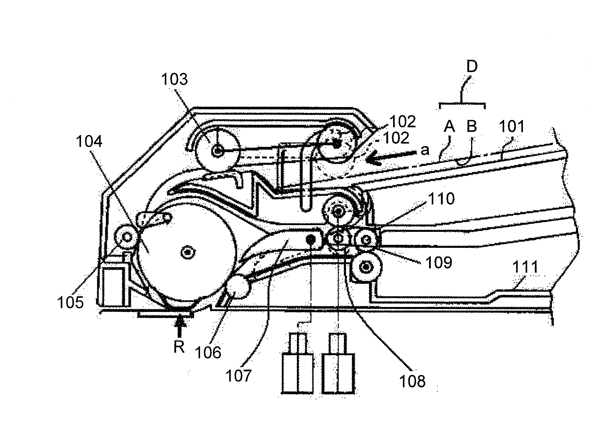
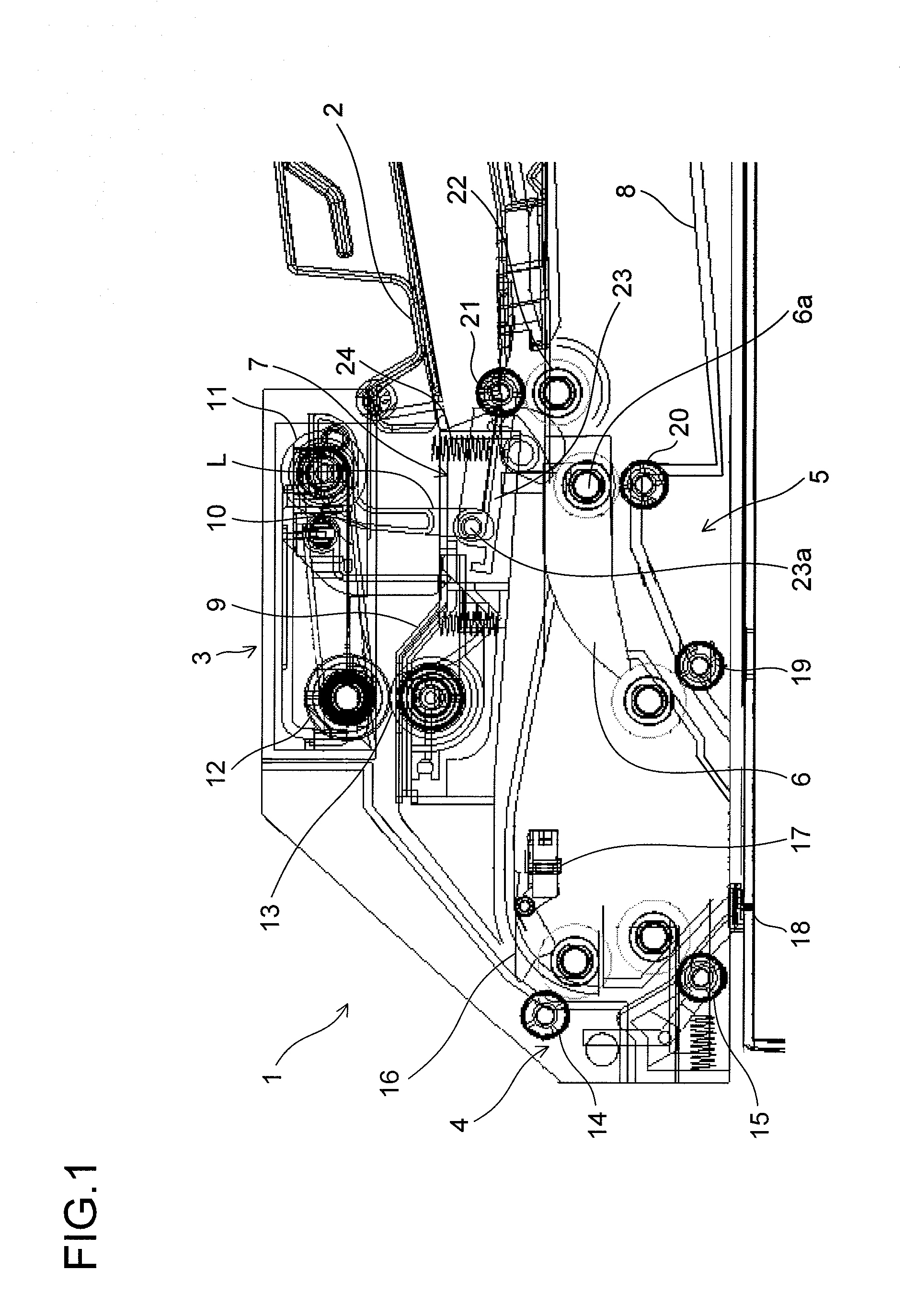
[0027]FIG. 1 is a cross-sectional view of the automatic document conveying device according to the embodiment of the present invention. In the following description, the left side of the figure is assumed to be a leading end of the automatic document conveying device and the right side of the figure is assumed to be a back end thereof.

[0028]As illustrated in FIG. 1, an automatic document conveying device (1) includes a document stacking tray (2) on which documents are to be placed, a document feeding portion (3) which supplies documents stacked on the document stacking tray (2) one by one, a conveying portion (4) which conveys...


PUM

PropertyMeasurementUnit
drive forceaaaaaaaaaa
rotationaaaaaaaaaa
optical pathaaaaaaaaaa

Abstract

Provided is an automatic document conveying device, including: a document feeding portion that feeds a document from a document stacking tray; a conveying portion that conveys the document which is fed, to a document reading portion; a discharge portion that discharges the document after being read to a discharge tray; a branching guide that switches a conveying path so that a second surface is read after a first surface of the document is read; and a switchback portion including a switchback roller pair for sending the document to the conveying portion again after the conveying path is switched by the branching guide, in which a switch of the conveying path by the branching guide and open/close of a nip of the switchback roller pair are performed in one drive portion.

Description

[0001]This application is based upon and claims the benefit of priority from the corresponding Japanese Patent Application No. 2010-009464 filed on Jan. 19, 2010, the entire contents of which are incorporated herein by reference.BACKGROUND OF THE INVENTION[0002]1. Field of the Invention[0003]The present invention relates to an automatic document conveying device that conveys a document to a reading position automatically, and an image forming apparatus including the automatic document conveying device.[0004]2. Description of Related Art[0005]As an automatic document conveying device used in a copier, a scanner, a facsimile, etc., there are well-known automatic document conveying devices in a form capable of inverting front and back surfaces of a document so as to read both surfaces of the document. In recent years, along with the downsizing of an image forming apparatus, there is also a demand for the downsizing of the automatic document conveying device as well as an image forming ...

Claims


Application Information

Patent Timeline
Patent Type & Authority Applications(United States)
IPC IPC(8): B65H5/06
CPCB65H29/58B65H85/00B65H2301/33312B65H2403/512B65H2404/1442B65H2405/3321B65H2404/1531H04N1/00578H04N1/0058H04N1/00602H04N1/0062H04N1/00631H04N1/00655B65H2801/39
Inventor HANAMOTO, KATSUHIKO
Owner KYOCERA DOCUMENT SOLUTIONS INC
Why Eureka
Try Eureka