
Solenoid valve system

A technology of solenoid valve and spool, applied in the field of solenoid valve system, to achieve common use, reduce the number of drives, and realize the effect of low cost

Active Publication Date: 2020-07-21
SMC CORP
View PDF10 Cites 0 Cited by
  • Summary
  • Abstract
  • Description
  • Claims
  • Application Information

AI Technical Summary

Problems solved by technology

Therefore, in the solenoid valve system, the life of the solenoid valve for exhaust is shorter than that of the solenoid valve for air supply.

Method used


Image

  • Solenoid valve system
  • Solenoid valve system
  • Solenoid valve system

Examples


no. 1 approach

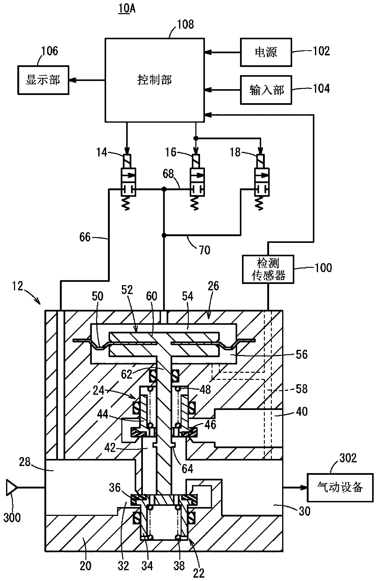
[0024] figure 1 The solenoid valve system of the first embodiment of the invention shown is used, for example, as an electropneumatic regulator for pressure control of the pneumatic device 302 based on an input signal.

[0025] Such as figure 1 As shown, the solenoid valve system 10A includes a valve main body 12 , an air supply solenoid valve 14 , a first exhaust solenoid valve 16 , and a second exhaust solenoid valve 18 . The valve main body 12 has a valve body 20 , an air supply valve portion 22 , an exhaust valve portion 24 , and a pilot valve portion 26 . A supply flow path 32 that communicates the inlet port 28 and the outlet port 30 with each other is formed in the valve body 20 . A gas supply source 300 for supplying compressed gas (for example, compressed air) is connected to the inlet port 28 . A pneumatic device 302 is connected to the outlet port 30 .

[0026] The air supply valve unit 22 opens and closes the air supply passage 32 . Specifically, the air suppl...

no. 2 approach

[0135] Next, a solenoid valve system 10B according to a second embodiment of the present invention will be described. In this embodiment, the same reference numerals are assigned to the same components as in the first embodiment, and description thereof will be omitted.

[0136] Such as Figure 13 As shown, the solenoid valve system 10B includes a valve body 200 instead of the valve body 12 . The valve main body 200 has a valve body 201 , an air supply valve portion 22 and a pilot valve portion 202 . A supply flow path 32 that communicates the inlet port 28 and the outlet port 30 with each other is formed in the valve body 201 .

[0137] The pilot valve unit 202 is a member for driving the air supply valve element 34 and is provided on the valve body 201 . The pilot valve unit 202 includes a diaphragm 50 that divides a predetermined space formed in the valve body 201 into a pilot chamber 54 and a back pressure chamber 56 , and a spool operating portion 52 provided on the di...


PUM


Abstract

A solenoid valve system (10A) includes a supply solenoid valve (14), a plurality of exhaust solenoid valves (16, 18), and a valve control section (126) controlling opening and closing operation of thesupply solenoid valve (14) and the plurality of exhaust solenoid valves (16, 18) using PWM or PFM. The plurality of exhaust solenoid valves (16, 18) are disposed in parallel with each other. The supply solenoid valve (14) and the plurality of exhaust solenoid valves (16, 18) have substantially identical flow rate characteristics. The number of the plurality of the exhaust solenoid valves (16, 18)is twice the number of the supply solenoid valve (14).

Description

technical field [0001] The present invention relates to solenoid valve systems. Background technique [0002] Japanese Patent Application Laid-Open No. 2005-157644 discloses a solenoid valve system comprising: an air supply spool that opens and closes the air supply passage connecting the inlet port and the outlet port; The valve part is used to drive the air supply spool. This solenoid valve system has a solenoid valve for gas supply and a solenoid valve for exhaust, wherein the solenoid valve for gas supply controls the flow rate of the gas supplied to the pilot chamber of the pilot valve part, and the solenoid valve for exhaust The valve controls the flow of gas discharged from the pilot chamber. The solenoid valve for air supply and the solenoid valve for exhaust are controlled by PWM control or PFM control to control the opening and closing operations. [0003] In the solenoid valve system as described above, it is preferable to use the same solenoid valves (solenoid...

Claims


Application Information

Patent Timeline
Patent Type & Authority Applications(China)
IPC IPC(8): F16K1/00F16K31/42F16K31/126F16K37/00
CPCF16K1/00F16K31/42F16K31/126F16K37/005G05D16/2095G05D16/2024F15B13/0426F15B13/043F16K31/02G05D7/0635G05B11/28G05B11/30F15B2211/575F15B1/26F15B13/021F15B2211/427F16K27/003F16K31/06
Inventor 仓田敏德久保博史
Owner SMC CORP
Learn More