
Redundant combustion engine starting systems for emergency generators

a technology for engine starting systems and generators, applied in the direction of engine starting, electric generator control, machines/engines, etc., can solve the problems of engine starting failure, long electricity cut-off, engine failure to start,

Inactive Publication Date: 2011-07-21
NAVETTA FR
View PDF7 Cites 39 Cited by
  • Summary
  • Abstract
  • Description
  • Claims
  • Application Information

AI Technical Summary

Benefits of technology

[0007]In an embodiment of the present disclosure, an engine-generator having an engine, an electrical generator and a control panel configured to control the engine-generator is provided. The engine-generator may include a first electrical starter having a first battery, a first solenoid configured to receive a starting signal from the control panel and a first starter motor configured to cran

Problems solved by technology

At times the cut-off of electricity is long and businesses depending on computers can not afford to be shut down because of the loss of power.
However, if the starter is defective or malfunctioning, the engine can not be started and, as such, power can not be supplied in emergency situations.

Method used


Image

  • Redundant combustion engine starting systems for emergency generators
  • Redundant combustion engine starting systems for emergency generators
  • Redundant combustion engine starting systems for emergency generators

Examples


Embodiment Construction

[0022]Particular embodiments of the present disclosure are described hereinbelow with reference to the accompanying drawings; however, it is to be understood that the disclosed embodiments are merely exemplary of the disclosure and may be embodied in various forms. Well-known functions or constructions are not described in detail to avoid obscuring the present disclosure in unnecessary detail. Therefore, specific structural and functional details disclosed herein are not to be interpreted as limiting, but merely as a basis for the claims and as a representative basis for teaching one skilled in the art to variously employ the present disclosure in virtually any appropriately detailed structure.

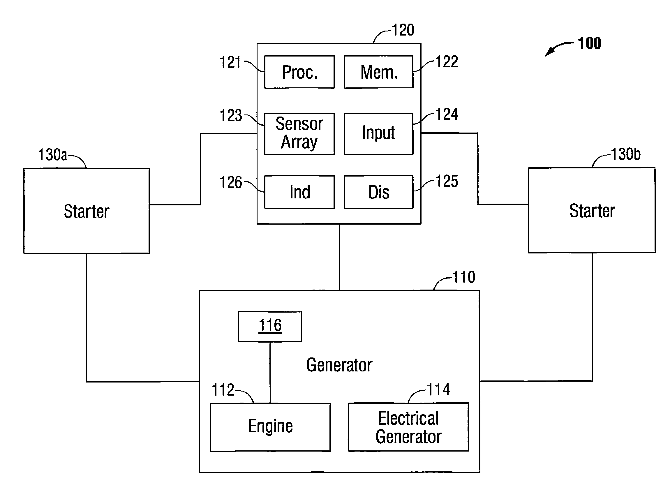
[0023]Turning to FIG. 1, a generator system according to an embodiment of the present disclosure is shown generally as generator system 100. Generator system 100 includes a generator 110 that may be an engine-generator or genset. Generator 110 is a combination of an engine 112 and an electrica...


PUM


Abstract

The present disclosure relates to an engine-generator having an engine, an electrical generator and a control panel configured to control the engine-generator. The engine-generator includes a first electrical starter having a first battery, a first solenoid configured to receive a starting signal from the control panel and a first starter motor configured to crank the engine when the first solenoid receives the starting signal from the control panel. The engine generator also includes a second electrical starter including a second battery, a second solenoid configured to receive a starting signal from the control panel and a second starter motor configured to crank the engine when the second solenoid receives the starting signal from the control panel.

Description

CROSS REFERENCE TO RELATED APPLICATIONS[0001]The present application claims priority to U.S. Provisional Application Ser. No. 61 / 296,292, filed Jan. 19, 2009, entitled “REDUNDANT COMBUSTION ENGINE STARTING SYSTEMS FOR EMERGENCY GENERATORS,” the contents of which are hereby incorporated by reference in their entirety.BACKGROUND[0002]1. Technical Field[0003]The present disclosure relates generally to engine starting systems for a generator. More particularly, the present disclosure is directed to an engine starting system that includes multiple starting systems to facilitate improved starting performance and redundant functionality to enhance engine starting reliability.[0004]2. Background of the Related Art[0005]Engine-powered electrical generators in fixed installations are used occasionally in emergency situations when the primary supply of electricity is disrupted as, for example, by storm or by high wind. These engine-powered electrical generators generate electricity in emergenc...

Claims


Application Information

Patent Timeline
IPC IPC(8): F02N11/04
CPCF02D29/06F02N11/0866F02N11/006F02N7/08F02N11/108F02N2300/2002
Inventor NAVETTA, FRANK
Owner NAVETTA FR
Learn More