

Ophthalmic photographing apparatus
- Summary
- Abstract
- Description
- Claims
- Application Information
AI Technical Summary
Benefits of technology
Problems solved by technology
Method used
Image

Examples
Embodiment Construction
[0031]Preferred embodiments of the present invention will be described below with reference to the accompanying drawings, in which like reference characters designate similar or identical parts throughout the several views thereof.
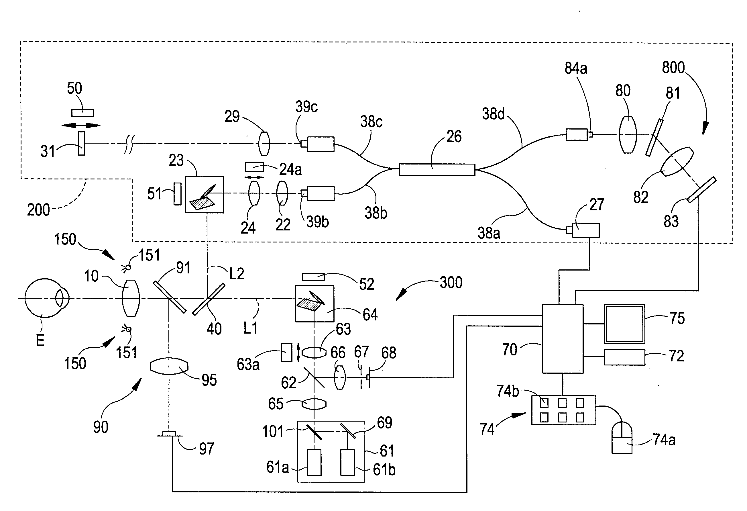
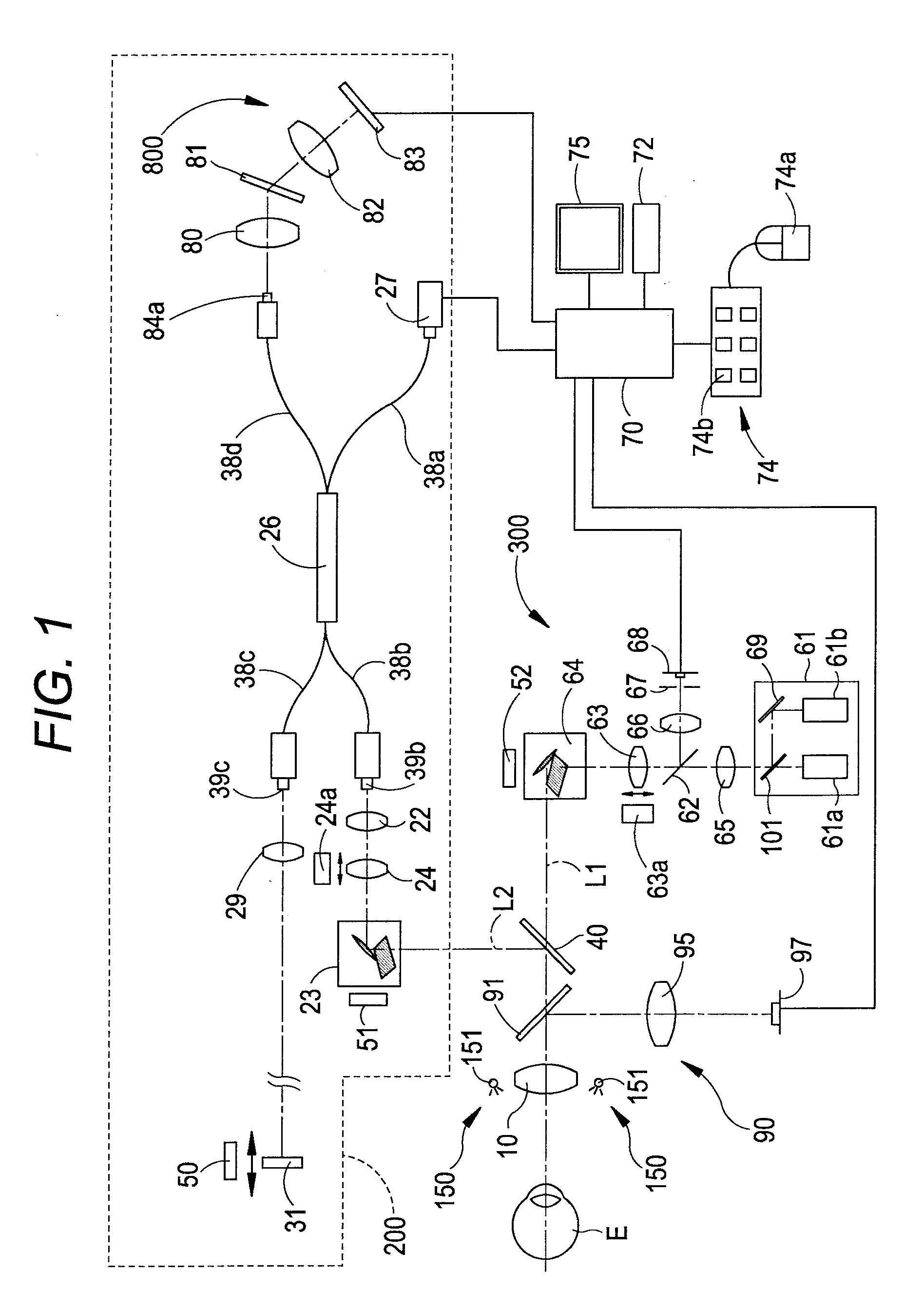
[0032]An embodiment in accordance with an aspect of the present invention will be described based on the drawings. FIG. 1 is a view showing an optical system and a control system in an ophthalmic photographing apparatus of the present embodiment. It is to be noted that in the present embodiment, a description is given with a depth direction of an examinee's eye referred to as a Z-direction (direction of optical axis L1), a horizontal direction referred to as an X-direction, and a vertical direction referred to as a Y-direction.
[0033]As shown in FIG. 1, the optical system of this ophthalmic photographing apparatus is broadly divided into an interference optical system (hereinafter referred to as OCT optical system) 200 and a scanning laser ophthalmoscope (S...
PUM
 Abstract
Description
Claims
Application Information