
Miter saw

a technology of miter saw and cutting blade, which is applied in the field of miter saw, can solve the problems of limited cutting capacity inability to cut more specifications workpieces, and inability of conventional miter saw to completely satisfy the requirements of operators, etc., and achieves improved cutting precision, compact structure, and improved cutting capacity of miter saw.

Inactive Publication Date: 2011-07-28
POSITEC POWER TOOLS (SUZHOU) CO LTD
View PDF12 Cites 5 Cited by
  • Summary
  • Abstract
  • Description
  • Claims
  • Application Information

AI Technical Summary

Benefits of technology

[0004]One object of the present invention is to provide a miter saw having a compact structure, a lower cost and a higher cutting capacity.
[0005]Another object of the present invention is to provide a miter saw having a higher cutting precision.
[0013]Compared with the prior arts, the present invention has some advantages. The second support member is movable with respect to the first support member to a plurality of predetermined working positions to perform cutting operation. Such that the cutting capacity of the miter saw is improved. The miter saw is able to cut more specifications of workpieces. The second support member is fixable at predetermined working positions to improve the cutting precision. In addition, the saw unit is connected to the worktable via the first support member and the second support member, the matching mechanism disposed between the first support member and the second support member has a guide groove and guide block, so the miter saw has a compact structure and a lower cost.

Problems solved by technology

But the distance between the pivot and the fence of the conventional miter saw keeps invariableness, so a cutting capacity of the conventional miter saw is limited.
That is to say, a admissible specification of the workpieces to be cut is limited to a certain range so the conventional miter saw isn't able to cut more specifications workpieces.
The conventional miter saw doesn't completely satisfy requirements of an operator.
But it is difficult to assure that the fence is perpendicular to a work surface of the worktable after the fence is moved relative to the worktable.

Method used


Image

  • Miter saw
  • Miter saw
  • Miter saw

Examples


Embodiment Construction

[0023]The present invention will be described in more details later with reference to the appended Figures and preferred embodiment.

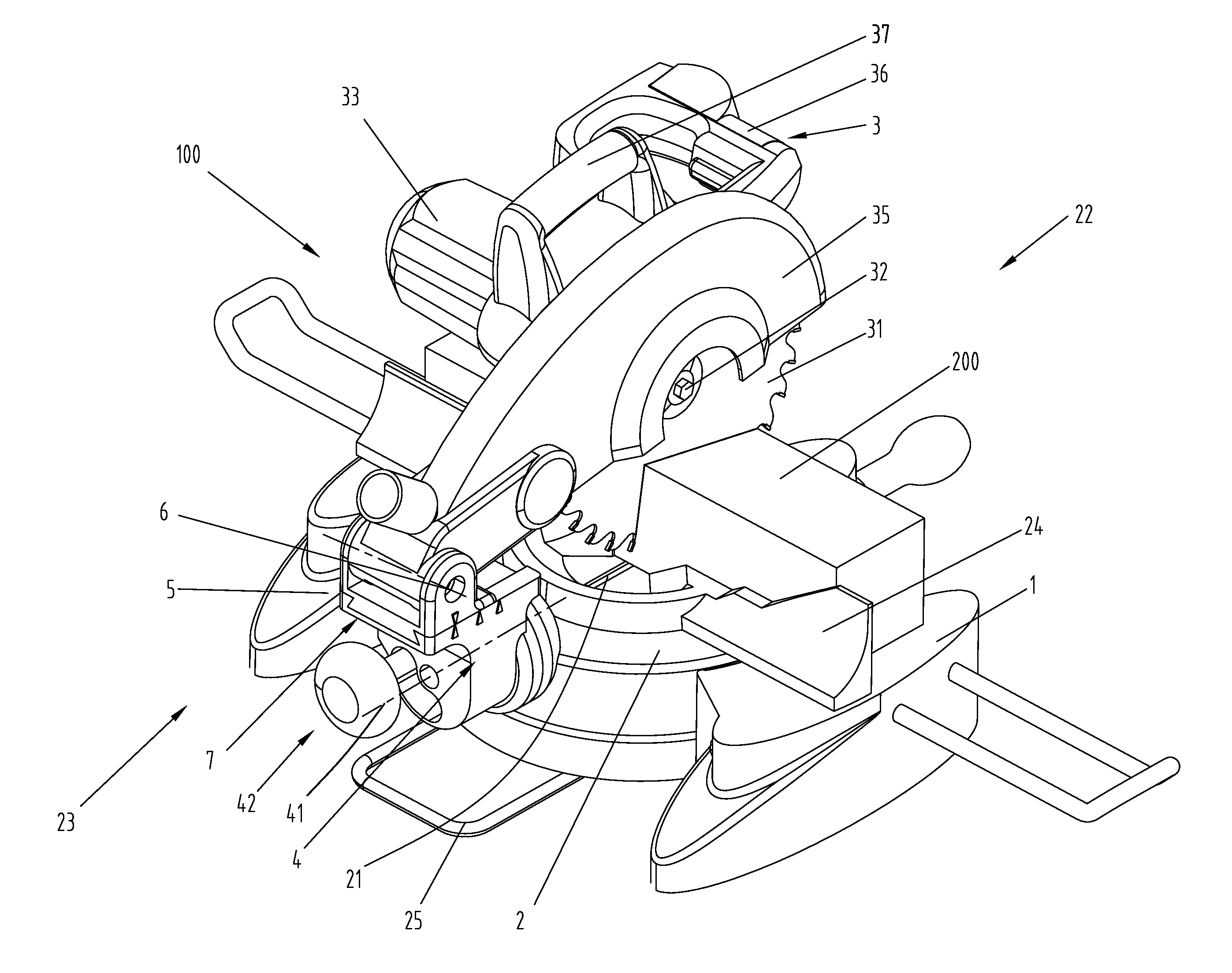
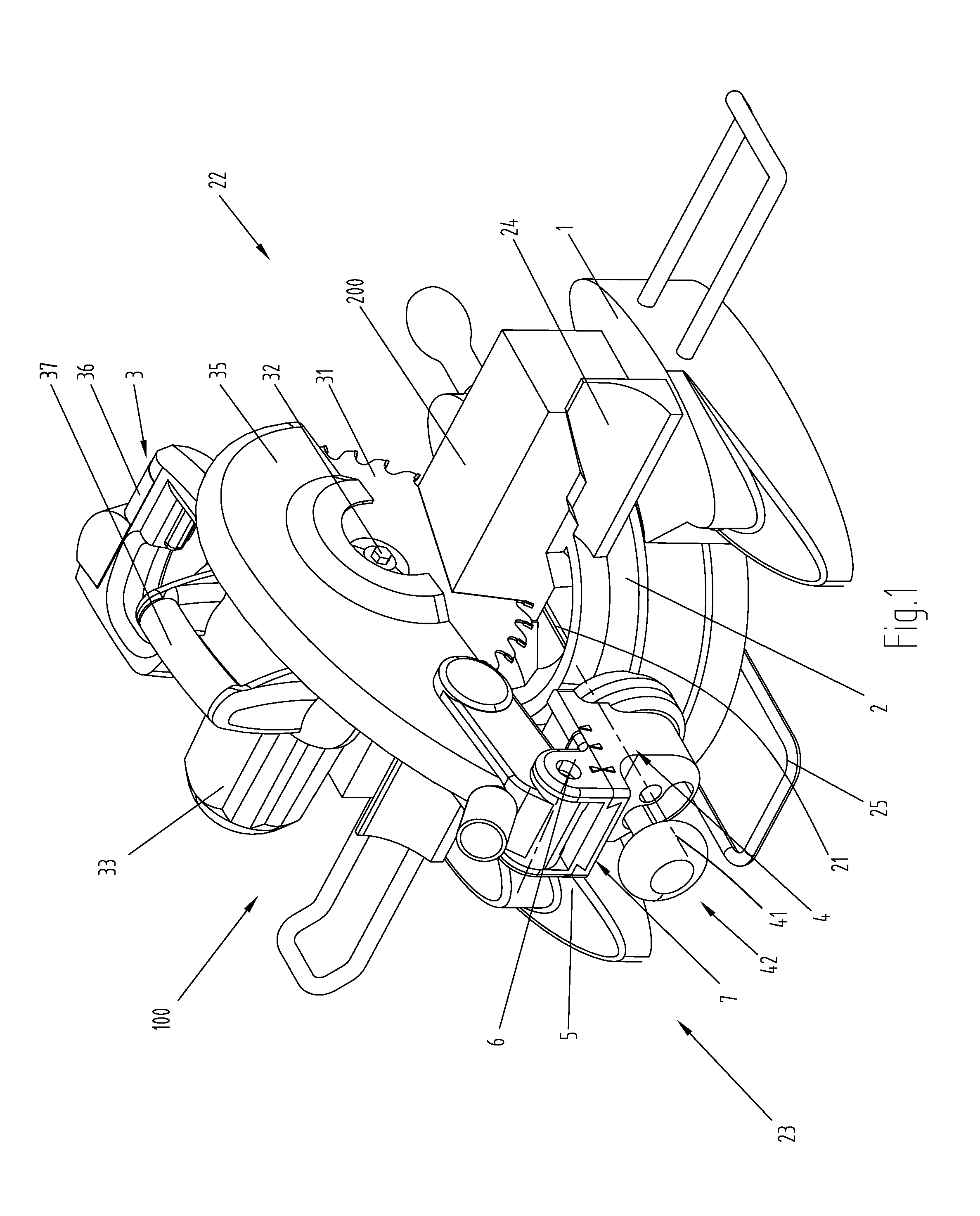
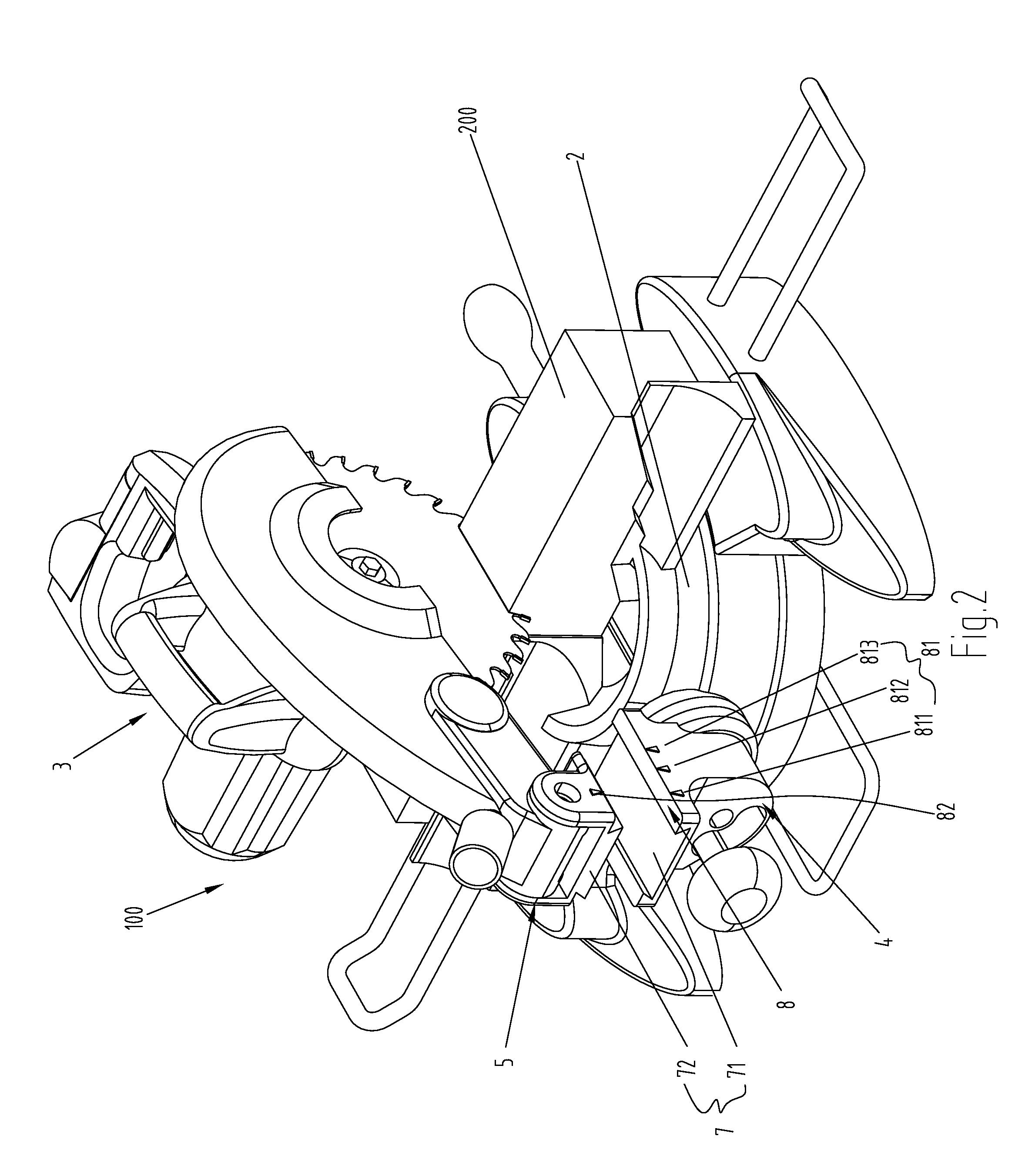
[0024]Referring to FIG. 1, a miter saw 100 comprises a base, a worktable 2 for supporting workpieces 200 to be cut, a first support member 4 attached to the worktable 2, a second support member 5 attached to the first support member 4, and a saw unit 3 attached to the second support member 5. The saw unit 3 is pivotally connected to the second support member 5 via a pivot 6, such that the saw unit 3 can be pivoted up and down relative to the base 1 to cut the workpieces vertically.

[0025]The first support member 4 defines a longitudinal axis 41, the first support member 4 is pivotable clockwise and anticlockwise to incline to a determined angle relative to the worktable 2 to cut the workpieces. A lock mechanism disposed between the first support member 4 and the worktable 2 locks the first support member 4 on the worktable 2.

[0026]The first support membe...


PUM

PropertyMeasurementUnit
Sizeaaaaaaaaaa

Abstract

A miter saw comprises a worktable; a first support member attached to the worktable; a second support member attached to the first support member; a saw unit pivotally connected to the second support member via a pivot; and a matching mechanism disposed between the first support member and the second support member, the matching mechanism is operated to cause the second support member to move with respect to the first support member, and the second support member is moved to reach a plurality of predetermined working positions to perform cutting operation. Thus, the cutting capacity of the miter saw is improved for the miter saw being able to cut workpieces with more specifications.

Description

FIELD OF THE INVENTION[0001]The present invention relates to a miter saw, and more particularly to a support device of the miter saw for supporting a saw unit.BACKGROUND OF THE INVENTION[0002]A conventional miter saw as a cutting tool has very wide using range. The miter saw is used for quickly and expediently cutting many metallic or nonmetallic materials. In general, the miter saw comprises a worktable, a saw unit having a motor and a blade disposed above the worktable, and a fence mounted on the worktable for stopping a workpieces. The saw unit is pivotally connected to the worktable via a pivot immovable with respect to the worktable. Therefore, the saw unit can cut the workpieces. But the distance between the pivot and the fence of the conventional miter saw keeps invariableness, so a cutting capacity of the conventional miter saw is limited. That is to say, a admissible specification of the workpieces to be cut is limited to a certain range so the conventional miter saw isn't ...

Claims


Application Information

Patent Timeline
IPC IPC(8): B23D47/04B23D45/04B23D45/14
CPCB27B5/29B23D45/044Y10T83/7693Y10T83/7697
Inventor BROWN, WARRENGERHARDT, GRAHAMSZOMMER, HARRY
Owner POSITEC POWER TOOLS (SUZHOU) CO LTD
Learn More