Electric grill and methods of providing the same
a technology of electric grills and electric grills, which is applied in the field of electric grills, can solve the problems of inconvenient and expensive purchasing of solid fuel, inability to meet the needs of electric grills, and inability to achieve the elevated temperature of electric grills, etc., and achieves the effect of preventing the inefficiency of electric grills from achieving the elevated temperatur
- Summary
- Abstract
- Description
- Claims
- Application Information
AI Technical Summary
Benefits of technology
Problems solved by technology
Method used
Image

Examples
fifth embodiment
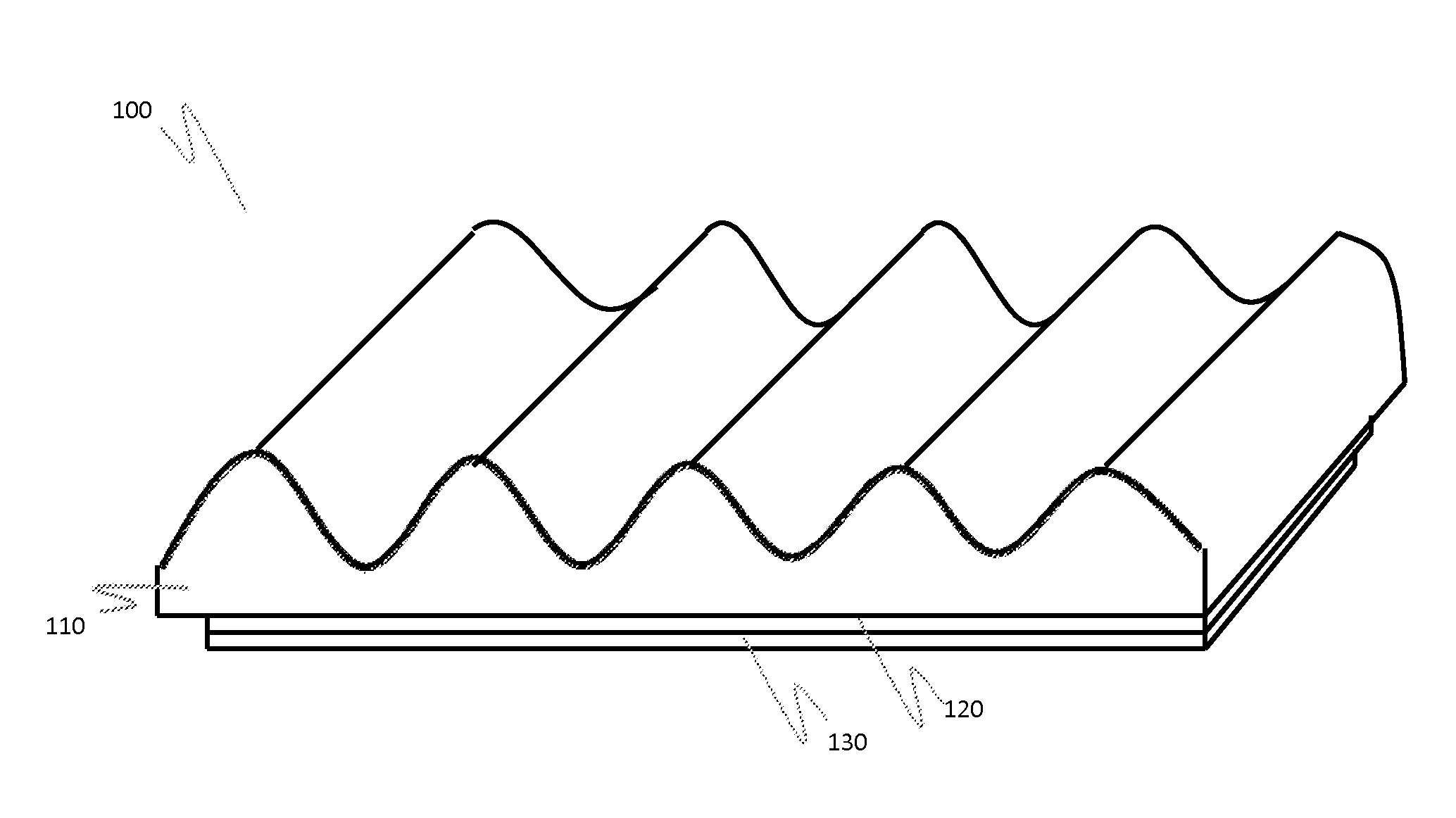
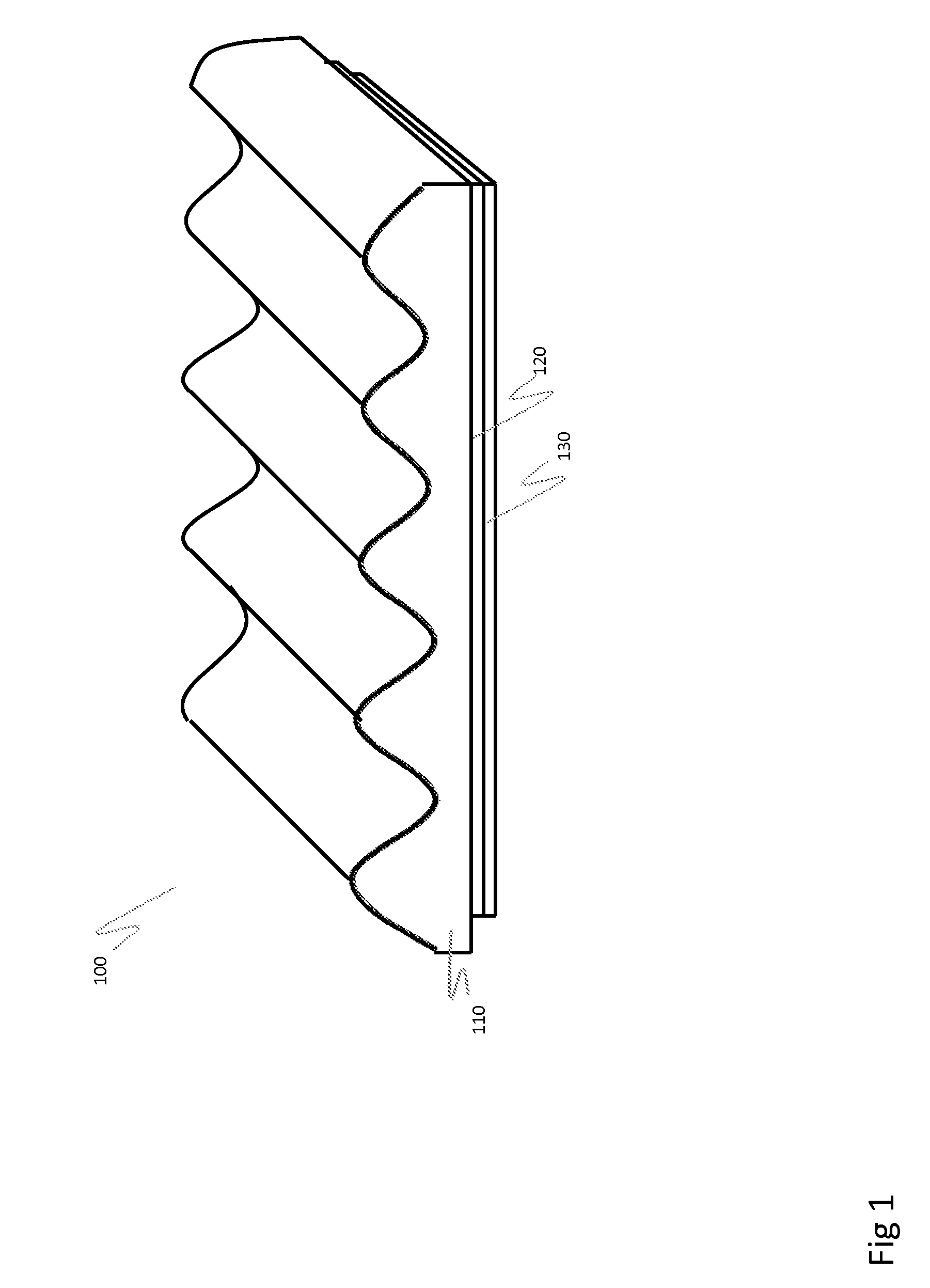
FIG. 6 is a schematic diagram illustrating an electric grill 500 according to the present invention. In this embodiment, the grill 500 is formed from a sheet of material, such as a metal sheet, that has been machined to produce a grate structure. In one embodiment, the sheet is a steel sheet, such as a 400 series stainless steel sheet, that has been machined by stamping the sheet to provide the grate structure. FIG. 6 is a top plan view of the grill 500, which includes a generally flat portion 510 extending around the edges of the grill and a series of parallel raised ridges 520 extending through the central area of the grill 500. The grill 500 can include open spaces 530 between the ridges 520 that allow fat and grease from a food product on the grill 500 to fall below the grill 500.
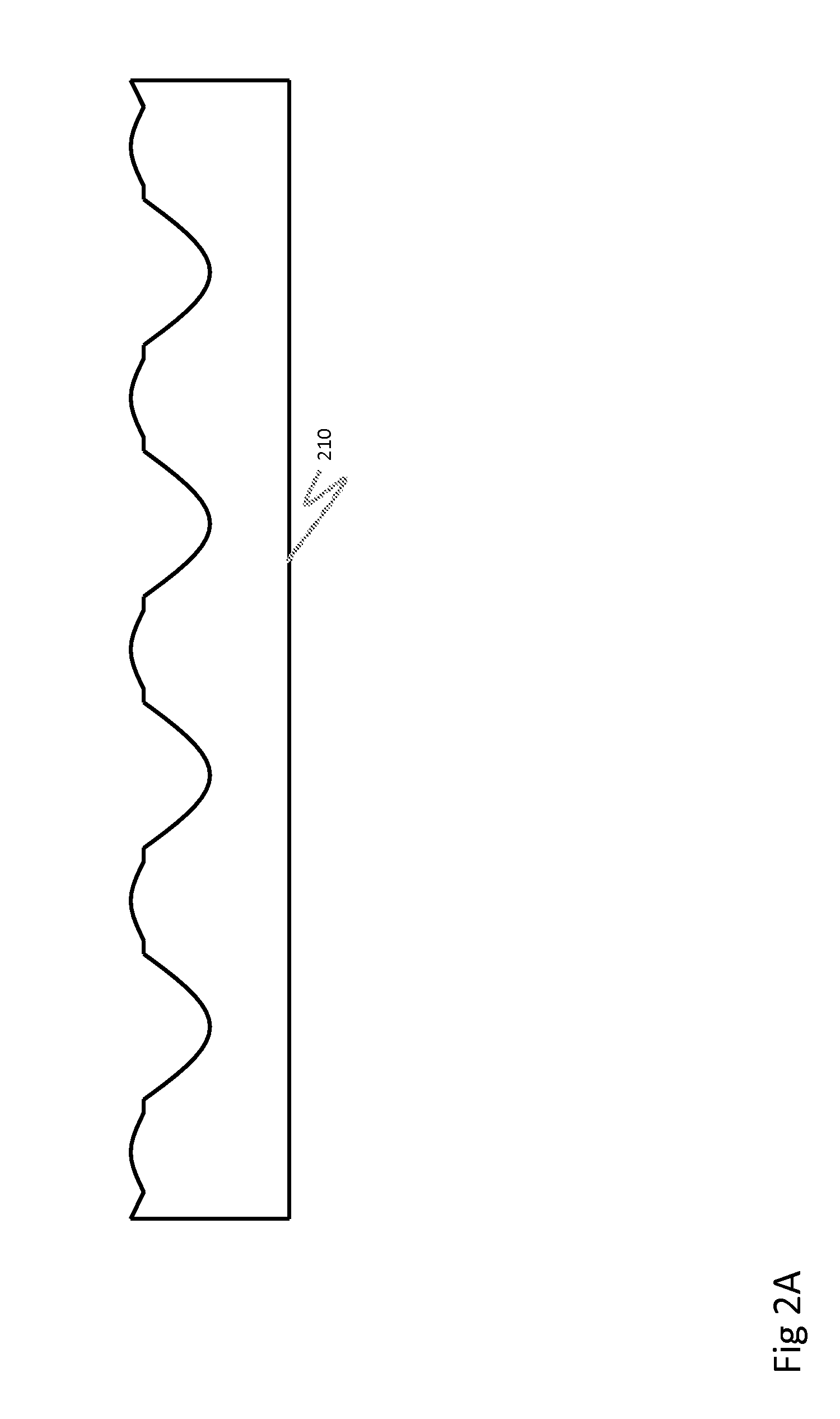
FIG. 7 is a cross section view of a plurality of ridges 520 separated by open spaces 530. In this embodiment, the ridges are relatively closely-spaced (e.g., about 3 / 16th of an inch apart), but it will ...
sixth embodiment
FIG. 10 illustrates an electric grill 600 according to the invention. In this embodiment, the grill 600 includes a cooking grate 610, which can be any conventional grill cooking surface, and a supporting tray 620 located beneath the grate 610, and holding a plurality of ceramic tiles or briquettes 630. A layered heating element 624, which can comprise a first insulating layer 621, a resistive heating layer 622, and a second insulating overcoat 623, such as described above in connection with FIGS. 1-9, is provided on at least one surface of the supporting tray 620. In the embodiment of FIG. 10, the layered heating element 624 is provided on the bottom surface of the tray 620, though it will be understood that the heating element can be provided on any surface(s) of the tray 620. When the heating element 624 is electrically energized, heat from the heating layer 622 is conducted to the briquettes 630, which, in turn, radiate heat upwards to the food positioned on the grate 610. The br...
seventh embodiment
FIG. 11 is a cross-sectional illustration of a grill 700 according to the invention. In this embodiment, the grill 700 includes a cooking grate 710, which can be any conventional grill cooking surface. The grate 710 is positioned on and supported by a bottom grill housing 720. A grill hood 730 can be positioned over the bottom grill housing 720 to provide an enclosed grill cavity. A heater panel 740 is attached to the grill hood 730 and suspended inside the grill cavity. A resistive heating layer 741 is provided on the heater panel 740. The use of a separate heater panel can be advantageous for ease of manufacture, to minimize capacitive leakage currents, and for ease of maintenance and replacement.
The heater panel 740 can be composed of an insulating material, and the resistive heating layer 741 can be deposited as a coating directly onto the panel 740. The resistive film heating layer can be deposited using any of the methods described above in connection with FIGS. 1-10. The pane...
PUM
| Property | Measurement | Unit |
|---|---|---|
| thickness | aaaaa | aaaaa |
| thickness | aaaaa | aaaaa |
| thickness | aaaaa | aaaaa |
Abstract
Description
Claims
Application Information
 - R&D
- Intellectual Property
- Life Sciences
- Materials
- Tech Scout
- Unparalleled Data Quality
- Higher Quality Content
- 60% Fewer Hallucinations
Browse by: Latest US Patents, China's latest patents, Technical Efficacy Thesaurus, Application Domain, Technology Topic, Popular Technical Reports.
© 2025 PatSnap. All rights reserved.Legal|Privacy policy|Modern Slavery Act Transparency Statement|Sitemap|About US| Contact US: help@patsnap.com