
Automatic and semi-automatic generation of image features suggestive of motion for computer-generated images and video

a technology of computer-generated images and features, applied in image data processing, instruments, computing, etc., can solve the problems of reducing the desired subtle detail, creating blurred appearance, and complicated animation sequences

Active Publication Date: 2011-07-28
DISNEY ENTERPRISES INC +1
View PDF7 Cites 68 Cited by
  • Summary
  • Abstract
  • Description
  • Claims
  • Application Information

AI Technical Summary

Benefits of technology

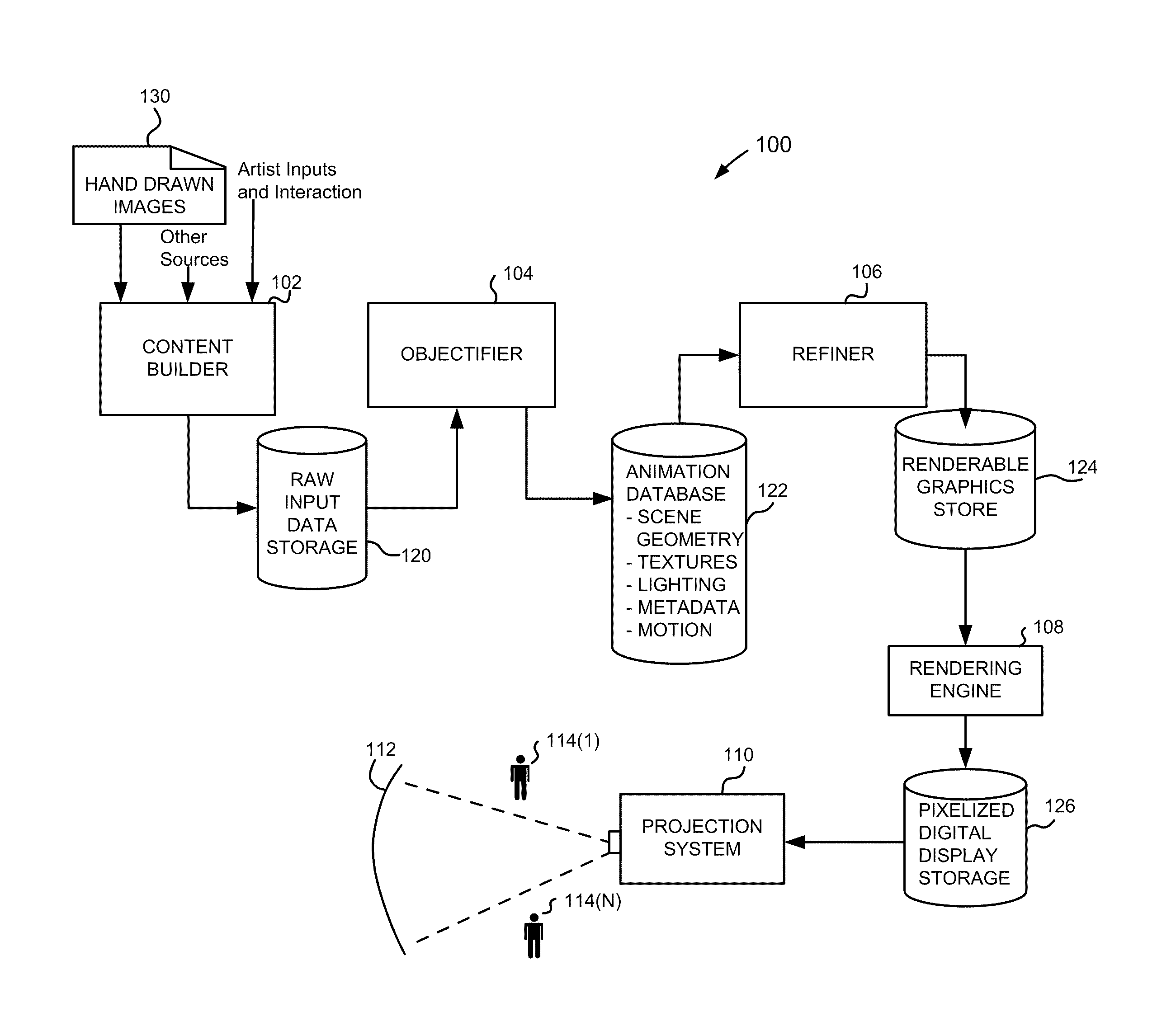
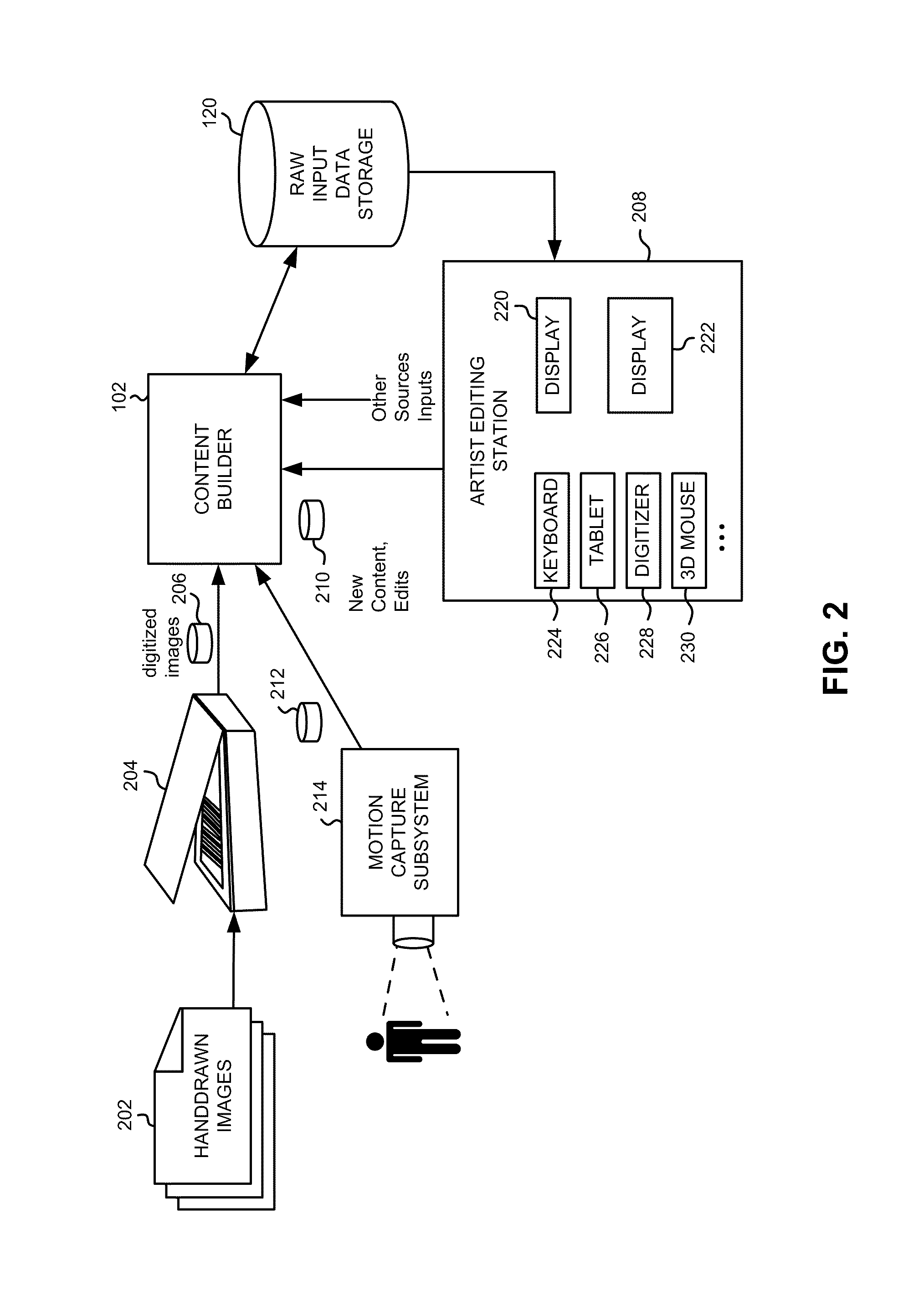
The patent describes an animation processing system that uses computer-generated images to create videos that can be shown on a screen. The system creates these images by using information about the scene and how it changes over time. The system can also use motion parameters and artist input to create specific effects. The system can adjust the colors of pixels in the images based on the movement of the scene and the type of effect being applied. Overall, the system allows for the creation of visually appealing and realistic videos.

Problems solved by technology

Of course, typically an animation sequence is more complicated than just a sphere, as it may have millions of objects, some moving and some not.
Nonphotorealistic rendering techniques for motion in computer games.
Due to the time it takes to expose a single frame of film, fast-moving objects will distribute their luminance over multiple locations of the film, thus creating a blurred appearance.
In fact, strict limitation to physical correctness and standard motion blur can tend to diminish the desired subtle detailing of motion in animations and might limit what an artist can easily do with an animation system.

Method used


Image

  • Automatic and semi-automatic generation of image features suggestive of motion for computer-generated images and video
  • Automatic and semi-automatic generation of image features suggestive of motion for computer-generated images and video
  • Automatic and semi-automatic generation of image features suggestive of motion for computer-generated images and video

Examples


example motion

Effects Programs

[0116]Some examples of motion effects programs, expressed in pseudocode are presented below. In these examples, a trace segment is comprises two end points, denoted ts.left and ts.right. the data structures representing each of the end points includes information about the animation time at which this surface location has been intersected by the view ray and linearly interpolated surface properties. They may be interpolated further with a function named INTERPOLATE( ), which takes a trace segment and a time at which it should be interpolated as parameters. The variable ts.center designates the interpolation of the end points' properties to the center of the segment. The SHADE( ) function evaluates the object's surface shader with the given surface parameters and returns its color. The animation time of the current frame being rendered is denoted as “current time.” The output of a motion effect program is a number of fragments, each with a color and coverage value, th...

example

Images

[0123]FIG. 10 illustrates different speed line styles. Customized styles can be achieved in a flexible manner, similar to the way programmable surface shaders are used to generate customized surface appearances. In FIG. 10(a), the ball is translating, whereas in FIGS. 10(b)-(c), the ball is also rotating. FIGS. 10(a)-(b) use a speed lines effect with a falloff function that fades in linearly at both ends of the speed lines and modulates the width of the speed line over time. For the image in FIG. 10(c), the distance of the seed point to the current pixel is used to manipulate the normal passed to the surface shader, giving a tubular appearance.

[0124]FIG. 11 illustrates a bouncing toy ball, rendered with a modified version of a motion blur effect. The effect program computes a reference time for the input trace, and uses the difference between this reference time and the current time to determine the amount of blur, or the shutter opening time in conventional terms. As a result...


PUM


Abstract

In an animation processing system, generating images to be viewable on a display using a computer that are generated based on scene geometry obtained from computer readable storage and animation data representing changes over time of scene geometry elements, but also images can be modified to include shading that is a function of positions of objects at other than the current instantaneous time for a frame render such that the motion effect shading would suggest motion of at least one of the elements to a viewer of the generated images. Motion effects provide, based on depiction parameters and / or artist inputs, shading that varies for at least some received animation data, received motion depiction parameters, for at least one pixel, a pixel color is rendered based on motion effect program output and at least some received scene geometry, such that the output contributes to features that would suggest the motion.

Description

CROSS-REFERENCES TO RELATED APPLICATION[0001]The present application claims benefit of priority under 35 USC §119(e) of Provisional Patent Application No. 61 / 296,459, filed on Jan. 19, 2010, titled “Automatic and Semi-Automatic Generation of Image Features Suggestive of Motion For Computer-Generated Images and Video”, the entire contents of which are herein incorporated by reference for all purposes.BACKGROUND[0002]The present invention relates to systems and methods for computer-generated image processing in general and in particular to altering a flow of a rendering image to allow for processing of inserted graphics elements that are frame specific and represent time-aggregation of other objects.[0003]It is well known that an animated visual presentation can be created by creating individual static images (frames). The static images, when displayed in sequence can form an animated visual presentation, such as a short sequence or a feature length film. Thus, each frame as a time at...

Claims


Application Information

Patent Timeline
Patent Type & Authority Applications(United States)
IPC IPC(8): G06T13/00
CPCG06T13/00
Inventor SUMNER, ROBERTGROSS, MARKUSTHUEREY, NILSOSKAM, THOMAS
Owner DISNEY ENTERPRISES INC
Learn More