Apparatus, system, and method for determining a read voltage threshold for solid-state storage media

Active Publication Date: 2011-07-28
SANDISK TECH LLC
View PDF99 Cites 151 Cited by
  • Summary
  • Abstract
  • Description
  • Claims
  • Application Information

AI Technical Summary

Benefits of technology

[0015]In one embodiment, the data set includes a sample data set read in response to a testing operation. In a further embodiment, the data set includes a requested data set read in response to a read request from a client. The data set, in certain embodiments, includes a requested data set and further includes an amount of additional data rea

Problems solved by technology

The read voltage levels of a storage cell, however, can shift over time.
For example, storage cell damage, storage cell leakage, and other disturbances to storage cells can alter the read voltage levels of the storage cells.
The rate of leakage and other disturbances can also i

Method used


Image

  • Apparatus, system, and method for determining a read voltage threshold for solid-state storage media
  • Apparatus, system, and method for determining a read voltage threshold for solid-state storage media
  • Apparatus, system, and method for determining a read voltage threshold for solid-state storage media

Examples


embodiment 300

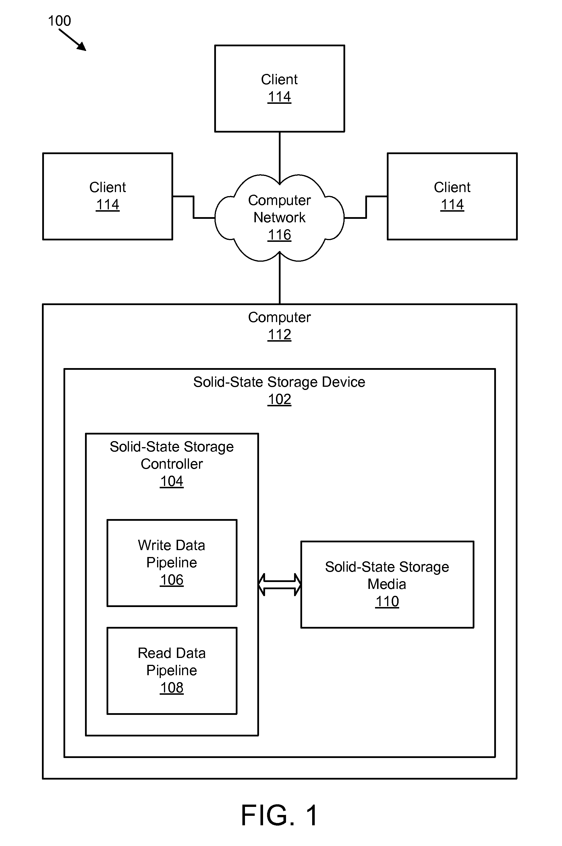
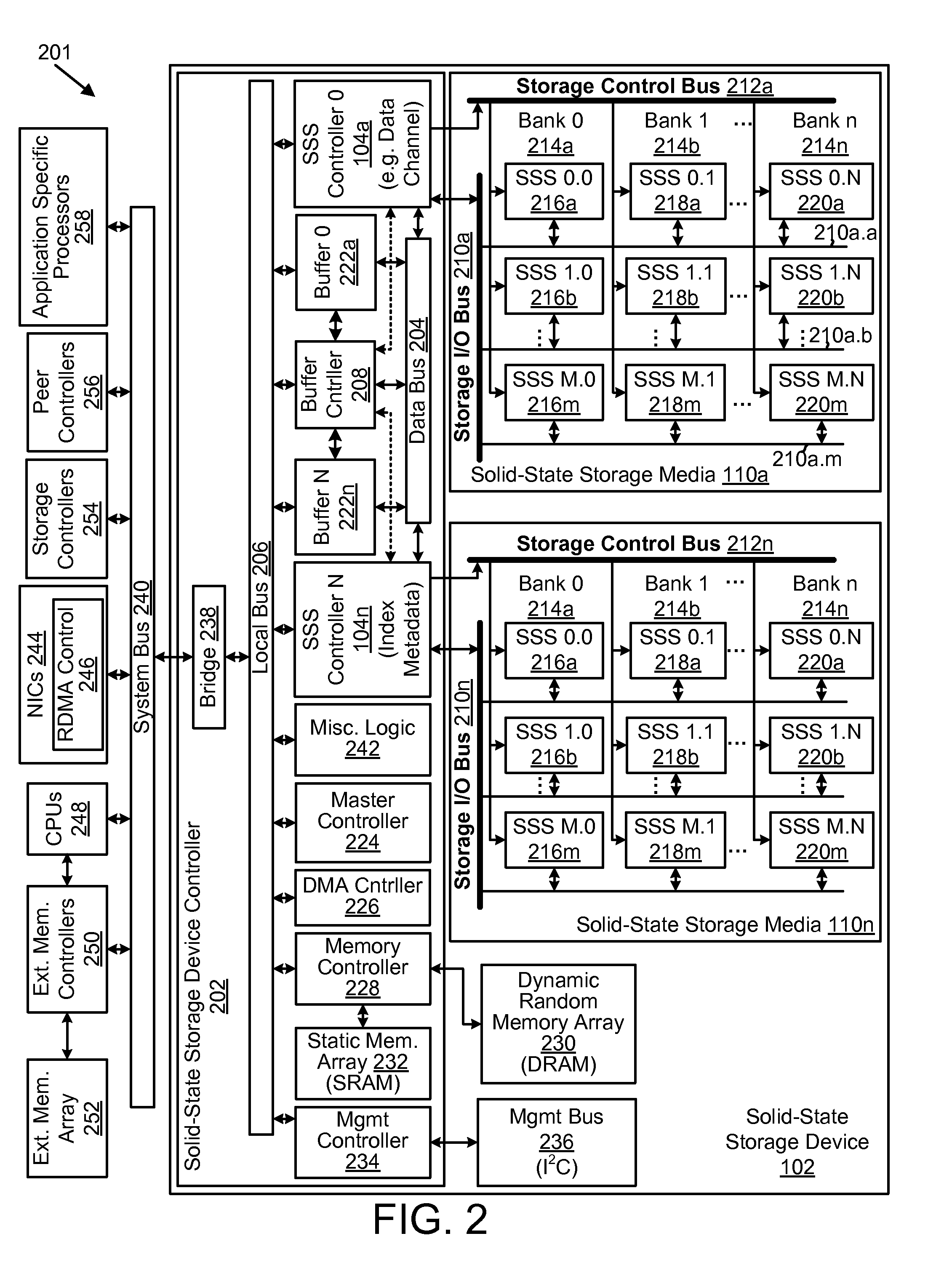
[0103]FIG. 3A is a schematic block diagram illustrating one embodiment 300 of a solid-state storage controller 104 with a write data pipeline 106 and a read data pipeline 108 in a solid-state storage device 102 in accordance with the present invention. The embodiment 300 includes a data bus 204, a local bus 206, and buffer control 208, which are substantially similar to those described in relation to the solid-state storage device controller 202 of FIG. 2. The write data pipeline 106 includes a packetizer 302 and an error-correcting code (“ECC”) encoder 304. In other embodiments, the write data pipeline 106 includes an input buffer 306, a write synchronization buffer 308, a write program module 310, a compression module 312, an encryption module 314, a garbage collector bypass 316 (with a portion within the read data pipeline 108), a bias module 318, and a write buffer 320. The read data pipeline 108 includes a read synchronization buffer 328, an ECC decoder 322, a depacketizer 324,...

embodiment 301

[0171]FIG. 3B is a schematic block diagram illustrating another embodiment 301 of a solid-state storage controller 104. In the depicted embodiment 301, the solid-state storage controller 104 includes a device factor module 354, the inverse bias module 332, the ECC decoder 322, and the read voltage module 352. Although not depicted in FIG. 3B, the solid-state storage controller 104 of the embodiment illustrated in FIG. 3B may also, in certain embodiments, include one or more additional modules or other elements from the solid-state storage controller 104 depicted in FIG. 3A, as described above.

[0172]In the depicted embodiment 301, the read voltage module 352 receives inputs from the inverse bias module 332, the ECC decoder 322, and the device factor module 354 and the read voltage module 352 determines a read voltage threshold adjustment 358 based on the inputs. In other embodiments, the read voltage module 352 may receive inputs from just the inverse bias module 332, from just the E...


PUM


Abstract

An apparatus, system, and method are disclosed for determining a read voltage threshold for solid-state storage media. A data set read module reads a data set from storage cells of solid-state storage media. The data set is originally stored in the storage cells with a known bias. A deviation module determines that a read bias for the data set deviates from the known bias. A direction module determines a direction of deviation for the data set. The direction of deviation is based on a difference between the read bias of the data set and the known bias. An adjustment module adjusts a read voltage threshold for the storage cells of the solid-state storage media based on the direction of deviation.

Description

CROSS-REFERENCE TO RELATED APPLICATIONS[0001]This application claims priority to U.S. Provisional Patent Application No. 61 / 298,861 entitled “APPARATUS, SYSTEM, AND METHOD FOR DETERMINING A READ VOLTAGE THRESHOLD FOR SOLID-STATE STORAGE MEDIA” and filed on Jan. 27, 2010 for John Strasser, et al. and to U.S. Provisional Patent Application No. 61 / 305,205 entitled “APPARATUS, SYSTEM, AND METHOD FOR DETERMINING A READ VOLTAGE THRESHOLD FOR SOLID-STATE STORAGE MEDIA” and filed on Feb. 17, 2010 for John Strasser, et al., both of which are incorporated herein by reference.BACKGROUND[0002]1. Field[0003]The subject matter disclosed herein relates to solid-state storage media and more particularly relates to read voltage thresholds for solid-state storage media.[0004]2. Description of the Related Art[0005]Many solid-state storage devices distinguish between different binary values that a storage cell may store based on a read voltage level of the storage cell. Solid-state storage devices may ...

Claims


Application Information

Patent Timeline
IPC IPC(8): G11C16/04G11C29/00G11C16/34
CPCG11C16/28G11C29/02G11C29/42G11C29/028G11C29/026G11C29/021
Inventor STRASSER, JOHNFLYNN, DAVIDFILLINGIM, JEREMYWOOD, ROBERT
Owner SANDISK TECH LLC
Why Eureka
Try Eureka