Attachment means

a technology of fixing means and nail placement tools, which is applied in the direction of fastening means, screws, threaded fasteners, etc., can solve the problems of damage to the surface of two-dimensional components, filler can only be applied with considerable effort, and the appearance of fixing means used with nail placement tools is often visual, so as to improve the visual appearance of building materials

Inactive Publication Date: 2011-07-28
RAIMUND BECK NAGELTECHNIK GMBH
View PDF16 Cites 7 Cited by
  • Summary
  • Abstract
  • Description
  • Claims
  • Application Information

AI Technical Summary

Benefits of technology

For the reasons specified above it is an object of the present invention to provide an attachment means for joining together two-dimensional components in dry construction by means of a placement tool which improves the visual appearance of the building material after the attachment means have been driven in.
In other words, by providing at least one concave curve in the head it is achieved that the filler which is applied when filling is held better by the head within the curve and accordingly grips better in the attachment region of the attachment means. In this way the formation of the most level possible surface by means of a filler is substantially simplified. It is therefore mostly possible to fill the entry points of the attachment means in just one working step. The individual entry points do not need to be treated repeatedly, and this is associated with a substantial saving of time.
In order to prevent a covering paper provided on the two-dimensional component from ripping when driving in the attachment means, in one exemplary embodiment of the present invention the head is formed such that its diameter widens conically from its end facing towards the shaft to its end facing away from the shaft. By means of the conical widening of the head it is achieved that the covering paper pierced by the point of the attachment means in the region of the head when the attachment means is driven in is expanded more gently, and this counters ripping of the covering paper.
In order to be able to draw the covering paper in even more cleanly when driving in the attachment means, in a further exemplary embodiment of the invention the head is provided on its end region facing towards the shaft with a circumferential punching or cutting edge. By means of this punching or cutting edge the hole made in the covering paper by the point is enlarged, in particular also punched or cut into the covering paper and then expanded on the covering paper by the conically widening round shape of the head, and drawn in cleanly beneath the face side facing towards the shaft in the region of the head without the paper ripping in the peripheral region of the hole.
Furthermore, the axis-parallel alignment of the groove makes it possible for the attachment means to be driveable into the combination of materials to be joined by an automatic nail gun substantially without any rotational movement.

Problems solved by technology

A disadvantage with the attachment means used with nail placement tools is often the visual appearance.
In particular, after driving in the placement nails either the entry points are damaged or the heads of the attachment means are clearly visible and mostly not flush with the surface of the building material to be attached so that the heads of the attachment means must subsequently be filled.
However, the problem is evident here that the filler can mostly only be applied with considerable effort so that an even surface is formed on the building material.
This is due to the fact, among other things, that the filler grips insufficiently onto the head of the attachment means mostly made of metal or plastic.
A further problem with the attachment means known in the prior art is that the surfaces of the two-dimensional components are often damaged when driving in the attachment means, and in particular covering papers provided on the surface of the two-dimensional components rip when driving in the attachment means, and this results in the necessity to fill the entry point of the attachment means over a large area.

Method used


Image

  • Attachment means
  • Attachment means
  • Attachment means

Examples


Embodiment Construction

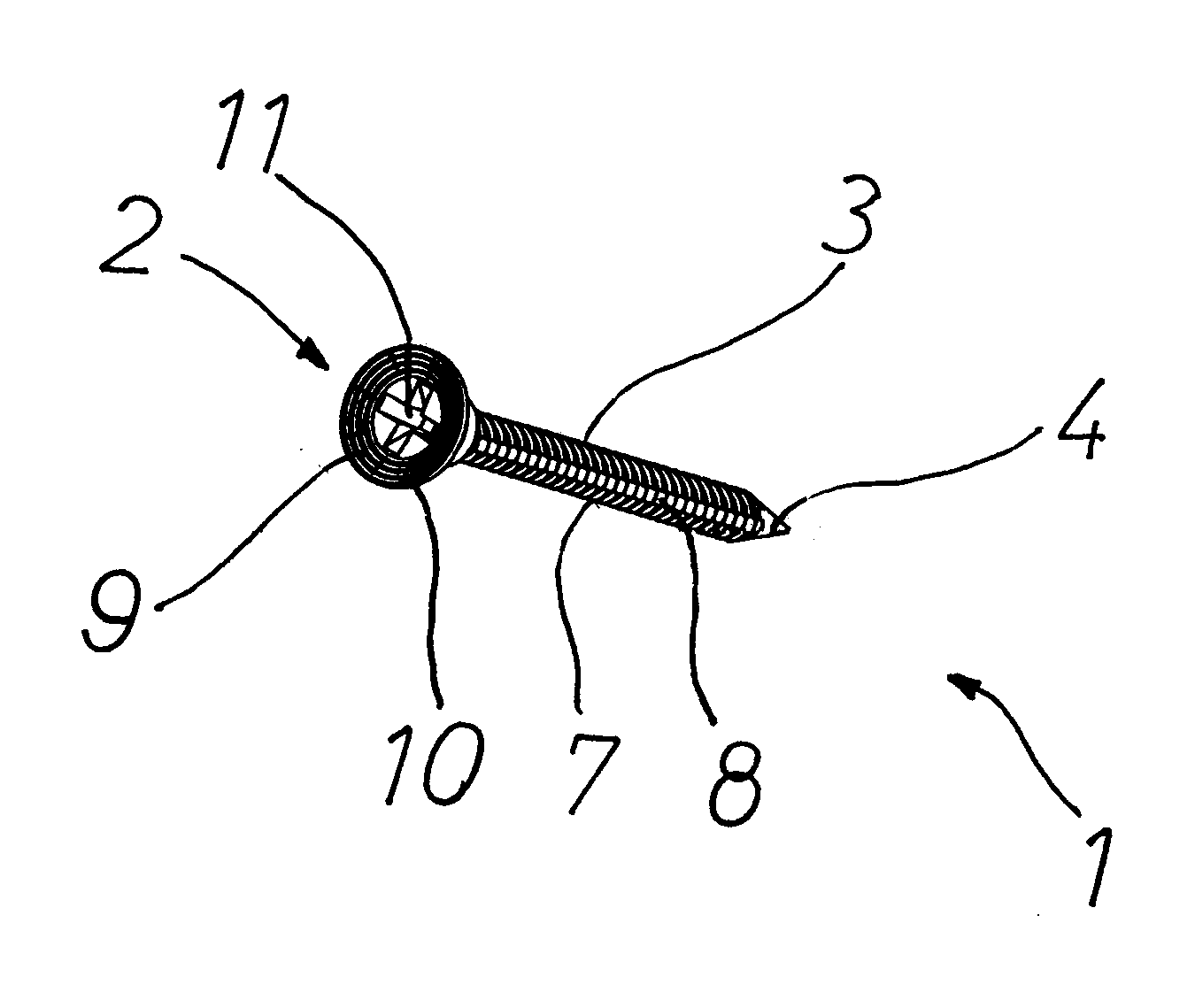
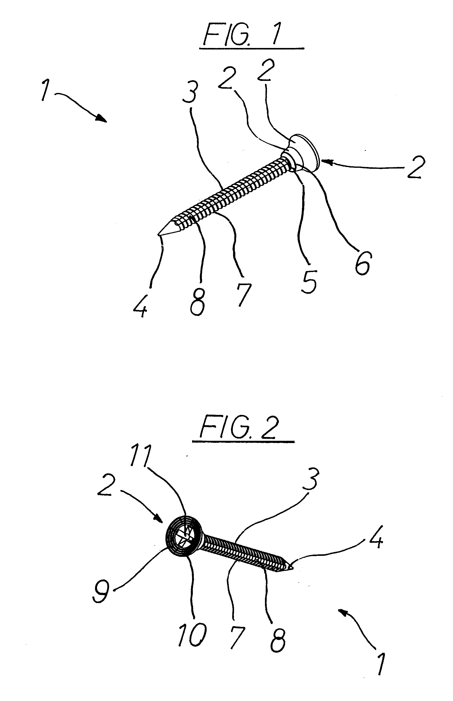
FIG. 1 shows a perspective illustration of an attachment means 1 according to the invention having a conically widening head 2.

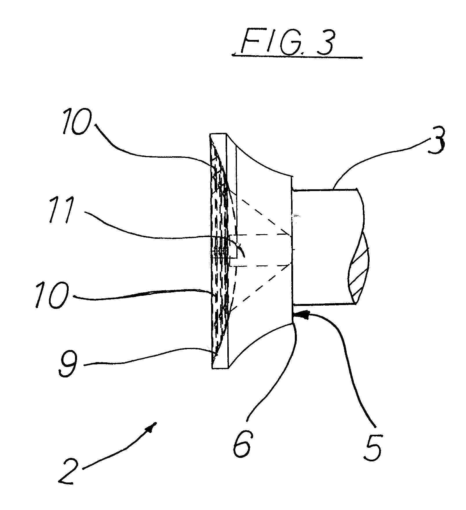
Here the attachment means 1 is designed in the form of a screw nail and serves to join together two-dimensional components in dry construction by means of a nail placement tool, in particular for fixing two-dimensional building material onto a metallic substructure. The attachment means 1 has a shaft 3 on one end region of which the conically widening head 2 is formed, and on the other end region of which a point 4 is provided. The head 2 has two sections 2a and 2b with different conicities. Here the conicities of the sections 2a and 2b differ in that the diameter of the head 2 increases more greatly from its end facing towards the shaft 3 to its end facing away from the shaft 3 in section 2b than in the upstream section 2a. In other words, the conicity chosen in section 2b is greater than in section 2a.

On a face side 5 of the head 2 facing towards the shaf...


PUM


Abstract

An attachment mean joins together two-dimensional components in dry construction by means of a placement tool, in particular for fixing two-dimensional building materials onto a metallic substructure. The attachment means has a shaft on one end region of which a point and on the other end region of which a head are formed. A face side of the head facing away from the shaft is formed with a concave curve.

Description

CROSS-REFERENCE TO RELATED APPLICATIONS AND CLAIM TO PRIORITYThis application is related to utility model application number 202010001325.9, filed Jan. 26, 2010 in the Federal Republic of Germany, the disclosure of which is incorporated by reference and to which priority is claimed.FIELD OF THE INVENTIONThe present invention relates to an attachment means for joining together two-dimensional components in dry construction by means of a placement tool, in particular for fixing two-dimensional building materials such as for example gypsum plasterboards or “DensGlas” boards onto a metallic substructure or a substructure made of wood, having a shaft on one end region of which a point and on the other end region of which a head are formed.BACKGROUND OF THE INVENTIONThese types of attachment means are generally known in the prior art. Specifically in dry construction it is preferable due to the plurality of attachment means to be fastened to introduce the latter into the two-dimensional b...

Claims


Application Information

Patent Timeline
Patent Type & Authority Applications(United States)
IPC IPC(8): F16B35/06F16B23/00
CPCF16B19/14
Inventor BECK, CHRISTIAN
Owner RAIMUND BECK NAGELTECHNIK GMBH
Why Eureka
Try Eureka