Flexible Cryogenic Probe Tip

a cryogenic probe and flexible technology, applied in the field of medical treatment technology, can solve the problems of inability to provide minimally invasive treatment or time-effective treatment options, current probe designs do not address real-time shaping or steering of the probe, etc., and achieve the effect of convenient proper placemen

Inactive Publication Date: 2011-07-28
ENDOCARE
View PDF20 Cites 24 Cited by
  • Summary
  • Abstract
  • Description
  • Claims
  • Application Information

AI Technical Summary

Benefits of technology

[0009]One embodiment of the invention is a flexible cryogenic probe tip. The flexible probe tip has a linear freeze zone at a distal end of the probe that allows for its placement and precisely controlled movements. The flexible cryogenic probe tip conforms to the target tissue surface to create a linear lesion. In addition, the probe tip is steerable to facilitate proper placement with minimal access points into a patient's body. Various configurations of the flexible probe tip, however, allow it to conform and ablate tissue of many sizes, shapes, and / or dimensions.

Problems solved by technology

Current probe designs do not address real-time shaping or steering of a probe while at the site of treatment or by any internal control mechanisms.
As such, the procedures to date cannot provide a minimally invasive treatment or time effective treatment option since the probes must be manually shaped and positioned repeatedly (with entry and withdrawal from a surgical cavity / opening) to achieve the proper placement.

Method used


Image

  • Flexible Cryogenic Probe Tip
  • Flexible Cryogenic Probe Tip
  • Flexible Cryogenic Probe Tip

Examples


Embodiment Construction

[0024]In the following detailed description, for purposes of explanation and not limitation, exemplary embodiments disclosing specific details are set forth in order to provide a thorough understanding of the present invention. However, it will be apparent to one having ordinary skill in the art that the present invention may be practiced in other embodiments that depart from the specific details disclosed herein. In other instances, detailed descriptions of well-known devices and methods may be omitted so as not to obscure the description of the present invention.

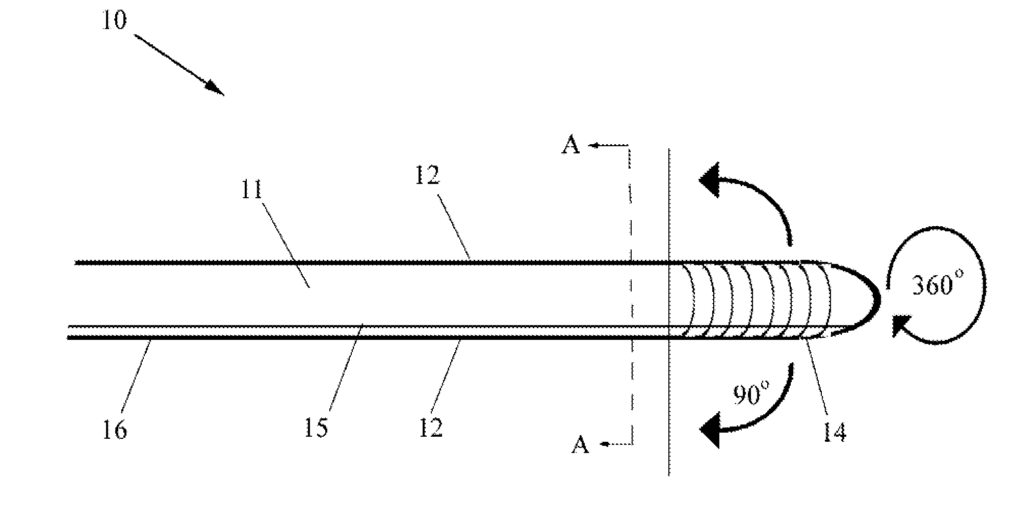
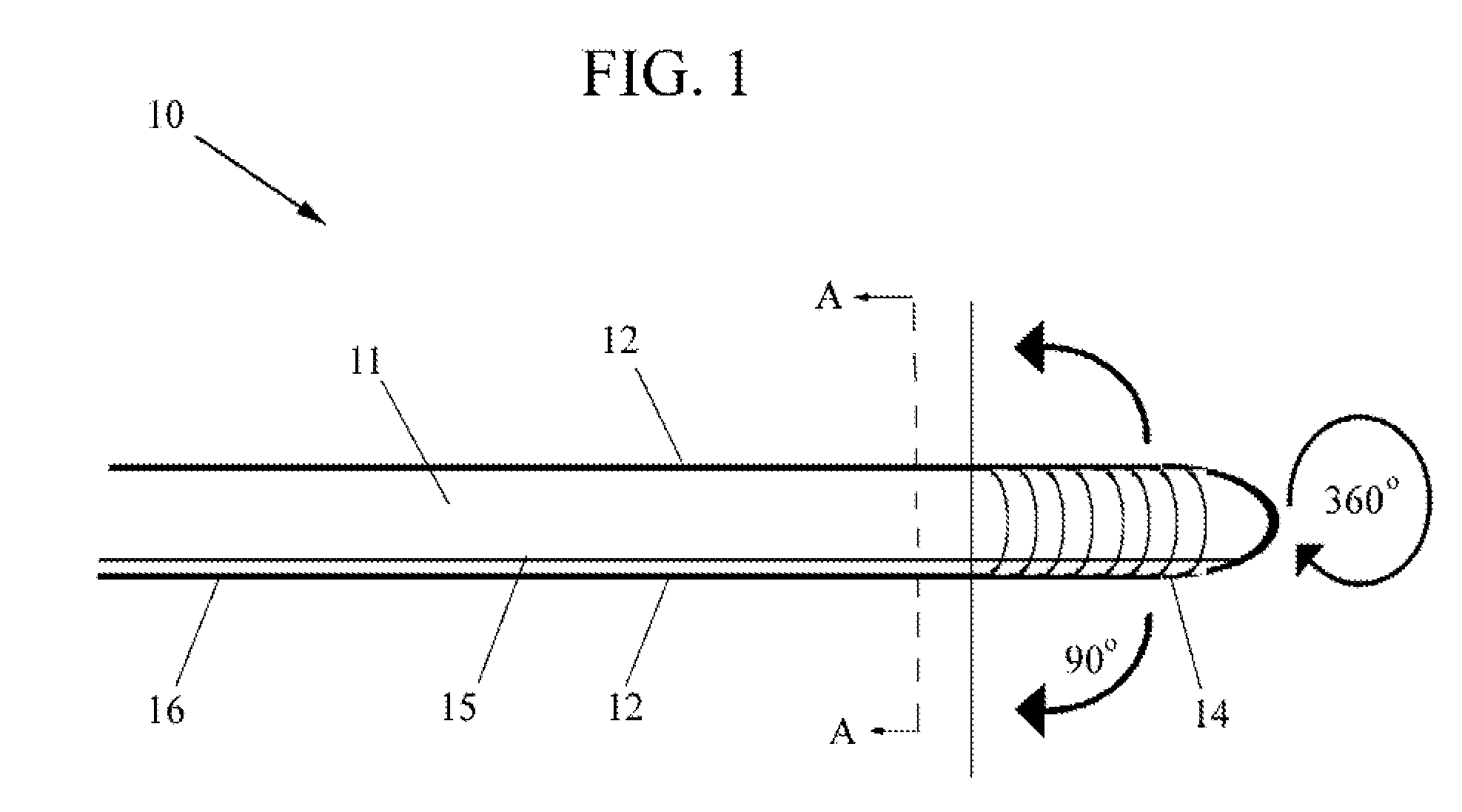
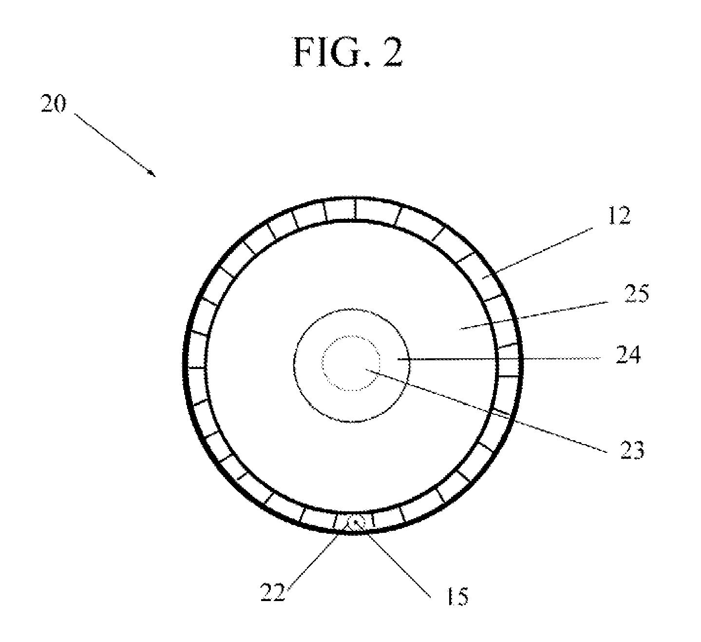
[0025]A perspective sideview of a flexible cryogenic ablation probe 10 in accordance with one embodiment of the present invention is illustrated in FIG. 1. The flexible probe 10 is a device 10 that comprises a body shaft 11 which is formed from sidewalls 12, a distal end 14 and proximal end 16. The distal end 14 is a highly flexible linear freeze zone and preferably integral with the body shaft 11. The distal end or tip 14...


PUM


Abstract

One embodiment of the invention is a flexible cryogenic probe tip. The flexible probe tip has a linear freeze zone at a distal end of the probe that allows for its placement and precisely controlled movements. The flexible cryogenic probe tip precisely conforms to the target tissue surface to create a linear lesion. In addition, the probe tip is steerable to facilitate proper placement with minimal access points into a patient's body. Various configurations of the flexible probe tip allow it to conform and ablate tissue of many sizes, shapes, and/or dimensions. Methods of utilizing the cryogenic probe tip include steps of positioning the distal end at a tissue site for at least one ablative procedure, maneuvering the distal end to the tissue site, directing a cryogen from the supply source to the distal end, controlling a flow of cryogen from the supply source to the distal end and back to the supply source, and segmenting control of the distal end mechanically or through the step of controlling the flow of cryogen.

Description

RELATED APPLICATIONS[0001]This is a nonprovisional patent application claiming benefit of International PCT Application No. US2009 / 062928 filed on Nov. 2, 2009 and titled A Cryogenic System and Method of Use under 35 U.S.C. §365(c), which claims priority to U.S. Non-provisional patent application Ser. No. 12 / 553,005 filed on Sep. 2, 2009, which claims priority to U.S. Provisional Patent Application Ser. No. 61 / 093,916 filed on Sep. 3, 2008, and titled Modular Pulsed Pressure Device for the Transport of Liquid Cryogen to a Cryoprobe, which is incorporated herein by reference; further claiming priority to U.S. Non-provisional patent application Ser. No. 12 / 562,301 filed on Sep. 18, 2009, which claims priority to U.S. Provisional Patent Application Ser. No. 61 / 098,244 filed on Sep. 19, 2008, and titled Nucleation Enhanced Surface Modification to Support Physical Vapor Deposition to Create a Vacuum, which is incorporated herein and also by reference; further claiming priority to U.S. Pr...

Claims


Application Information

Patent Timeline
Patent Type & Authority Applications(United States)
IPC IPC(8): A61B18/02
CPCA61B18/02A61B2018/0212A61B2017/003A61B2017/00084A61B2018/00202A61B2018/00208A61B2018/00577A61B2018/00797
Inventor BAUST, JOHN M.BAUST, JOHN G.CHEEKS, ROYROBILOTTO, ANTHONY T.LUECKGE, CLAUDIA
Owner ENDOCARE
Why Eureka
Try Eureka