Decorative jewelry double clasp with single spring for bracelets & necklaces

a double-action, jewelry technology, applied in the field of single-action double-action clasps, can solve the problems of requiring double the effort to remove both ends of the chain, difficult opening and closing, and broken jewelry chains, and achieves the effects of simple mechanism, fine, delicate and ornamental appearance, and high stability and security

Inactive Publication Date: 2011-08-04
PINCHUK ANNA
View PDF19 Cites 9 Cited by
  • Summary
  • Abstract
  • Description
  • Claims
  • Application Information

AI Technical Summary

Benefits of technology

[0008]It is, therefore, a primary object of the present invention to provide a jewelry clasp that uses a single-pivot spring-biased hinge for double-sided locking of opposing ends of a chain together. Another object of the present invention is to provide a double-sided jewelry clasp with a fine, delicate and ornamental appearance, but which is highly stable and secure.
[0009]It is still another object of the present invention to provide a double-sided jewelry clasp with a simplified mechanism using minimal moving parts (four), and which is simple and efficient to manipulate.
[0010]It is still another object to provide a double-sided jewelry clasp with no fragile parts or stress points prone to breakage.
[0011]In accordance with the foregoing objects, the present invention is a double-sided jewelry clasp having a rocker plate pivotally mounted to a base plate at a spring-biased hinge. The hinge comprises a pair of opposing yokes extending from the center of each of the rocker plate and base plate. With the rocker plate facing the base plate, the yokes align and a pin is inserted through distal apertures in all of the yokes to pivotally secure them together. A torsion spring is carried on the pin to bias the rocker plate versus the base plate. Further, the base plate has a hook at one end and a post at the other. The post acts as a stop against the pivoting of the rocker plate, and as a yoke for insertion of one end of a necklace or other chain. Thus, when the rocker plate is pivoted tight against the necklace chain is held captive on the post. The hook loops around to the backside of the rocker plate, and thereby acts as a stop against the counter-pivoting of the rocker plate. Likewise, the hook serves as a yoke for insertion of the other end of the necklace. Thus, when the rocker plate is counter-pivoted tight against the hook the necklace chain is held captive on the hook. Given a spring-bias the rocker plate will seat against both the post and hook, locking the necklace chain at both ends. A user need only depress the rocker plate to counter-bias it open at both ends, and thereby release both ends of the necklace chain. The foregoing configuration accomplishes a double-ended yoke / release with just a single-spring-biased hinge, minimal parts (four), and no stress points prone to breakage. The result is a double-sided jewelry clasp that is highly stable and secure, yet which presents a fine, delicate ornamental appearance. Moreover, it is simple and efficient to manipulate.

Problems solved by technology

The delicate nature of these clasps makes opening and closing difficult, and struggling with the clasp can easily break the jewelry chain under the strain of opening.
However, each set of interlocking fastening means is completely independent of the other, and as such requires double the effort to remove both ends of the chain.
Moreover, the two interlocking fastener are compression fittings which require significant dexterity to manipulate.
Compression fittings are not well suited for very fine smaller jewelry.
If the metal yokes fail are too small they tend to break.

Method used


Image

  • Decorative jewelry double clasp with single spring for bracelets & necklaces
  • Decorative jewelry double clasp with single spring for bracelets & necklaces
  • Decorative jewelry double clasp with single spring for bracelets & necklaces

Examples


Embodiment Construction

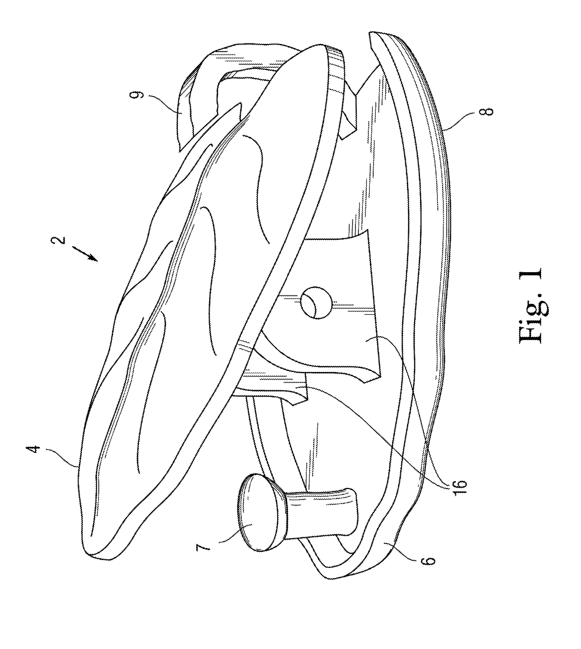
[0017]The present invention is a jewelry clasp with a more efficient single-pivot spring-biased hinge for double-sided locking of opposing ends of a chain together.

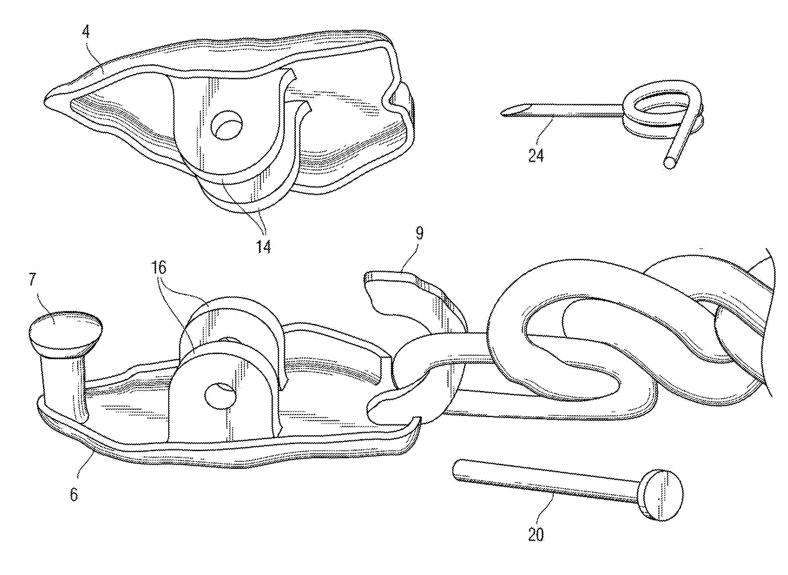
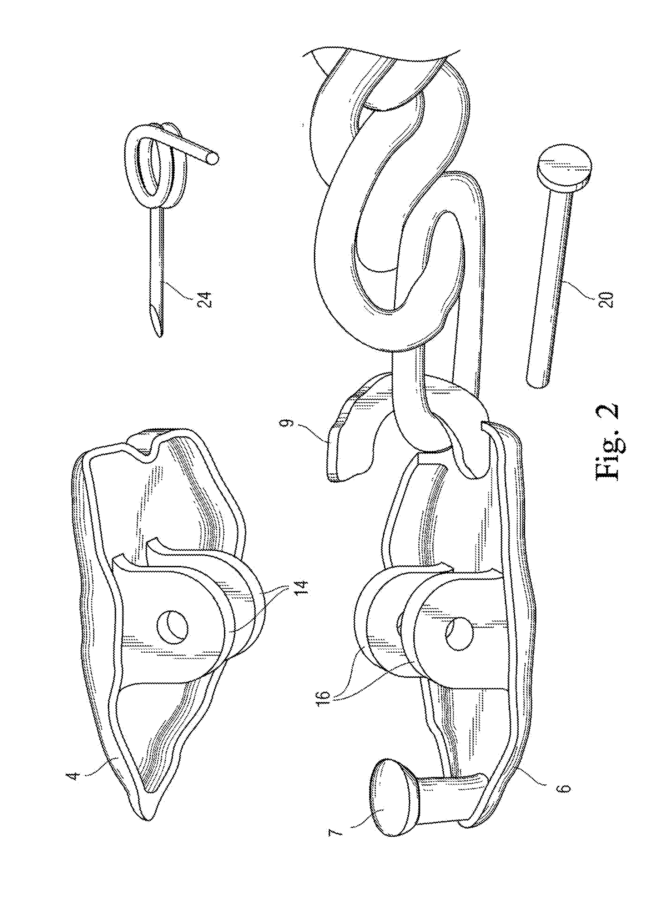
[0018]FIG. 1 shows a perspective view of an embodiment of the jewelry clasp 2 in an open position ready for insertion of both ends of a chain, while FIGS. 2-3 are exploded / disassembled views illustrating the individual components. With collective reference to FIGS. 1-3, the double-sided jewelry clasp 2 generally comprises a rocker plate 4 offset from and pivotally mounted atop a base plate 6 in a facing relation, at a centrally-located spring biased hinge 8. Both rocker plate 4 and base plate 6 may be formed in any of a variety of ornamental shapes, including complementary leaves as shown. They need not be uniform or flat, but must facilitate pivoting of rocker plate 4. The offset hinge 8 further comprises an opposing pair of yokes 14, 16 extending from the center of each of the rocker plate 4 and base plate 6, respective...


PUM


Abstract

A decorative double-sided jewelry clasp for joining two ends of a jewelry chain together. The clasp comprises a rocker plate pivotally mounted to a base plate at a hinge. The hinge is formed by cooperating yokes extending from the center of each of the rocker plate and base plate. With plates facing, the yokes align and a pin is inserted there through to pivotally secure them together. A torsion spring is carried on the pin to bias the rocker plate versus the base plate. Further, the base plate has a short post at one end and a longer hook at the other, the hook looping around to the backside of the rocker plate, and thereby stopping counter-pivoting of the rocker plate. Both hook and post catch and secure the ends of the jewelry chain, with the spring locking the chain at both ends until a user depresses the rocker plate, thereby counter-biasing it open at both ends to release the chain.

Description

CROSS REFERENCE TO RELATED APPLICATIONS[0001]The present application derives priority from U.S. provisional application 61 / 336,996 filed 29 Jan. 2010 which is incorporated herein by reference.BACKGROUND OF THE INVENTION[0002]1. Field of the Invention[0003]The present invention relates generally to jewelry clasps and, more particularly to a single-action double clasp for attaching bracelet and necklace chains in a loop using a single spring.[0004]2. Description of the Background[0005]Clasping devices for necklaces, bracelets and other looped jewelry are well known in the art. They range from a very simple split-ring construction and operation, to more complex double-locking clasps. Most all such jewelry clasps are used to connect the free ends of necklace chains, bracelet chains, ankle chains, and the like. The very nature of these clasps and their use with delicate aesthetic chains commands a very small, delicate ornamental appearance, with tiny but stable and secure double-locking ...

Claims


Application Information

Patent Timeline
Patent Type & Authority Applications(United States)
IPC IPC(8): A44C5/18F16B2/10
CPCA44C5/18Y10T24/44333F16B2/10A44C5/20A44C5/2019
Inventor PINCHUK, ANNA
Owner PINCHUK ANNA
Why Eureka
Try Eureka