Pneumatically Powered Impact Device and Method

a pneumatic and handheld technology, applied in the direction of manufacturing tools, portable drilling machines, building rescue, etc., can solve the problems of insufficient power, design suffer from several, and the battering ram is generally too heavy to operate, so as to achieve a higher peak force and high striking velocity

Inactive Publication Date: 2011-08-04
RAPID ENTRY SOLUTIONS
View PDF23 Cites 1 Cited by
  • Summary
  • Abstract
  • Description
  • Claims
  • Application Information

AI Technical Summary

Benefits of technology

[0005]To operate the device of the present invention to knock down a barricade such as a door, for example, the rear handle operator is lifted to allow a portion of the compressed fluid (e.g., air) to be released from the container into the charge cavity. The impact device is then swung at the barricade such that the striker assembly hits the barricade, which causes the rod to be pushed against the sear block, thereby raising the sear arm so as to release the piston. The piston then releases through the object-striking end of the impact device. As a result, the piston head hits the barricade with an effectively high striking velocity, thereby imparting a higher peak force for exploding through the barricade. The device of the present invention can be quickly re-set, automatically or manually, in order to permit multiple subsequent strikes against the target object as necessary.

Problems solved by technology

Battering rams generally suffer from being too heavy to operate and failing to provide enough power to break open a door on the first shot.
However, such designs suffer from several disadvantages.
First, the supply of compressed air is located internally and is therefore not rapidly interchangeable.
Second, the sear mechanisms are generally unstable and of poor mechanics.
Third, the venting and charging of gases in Gillespie is not easily managed by the end user, which can result in delays in re-charging or re-setting the device that can translate into negative consequences for the user.

Method used


Image

  • Pneumatically Powered Impact Device and Method
  • Pneumatically Powered Impact Device and Method
  • Pneumatically Powered Impact Device and Method

Examples


Embodiment Construction

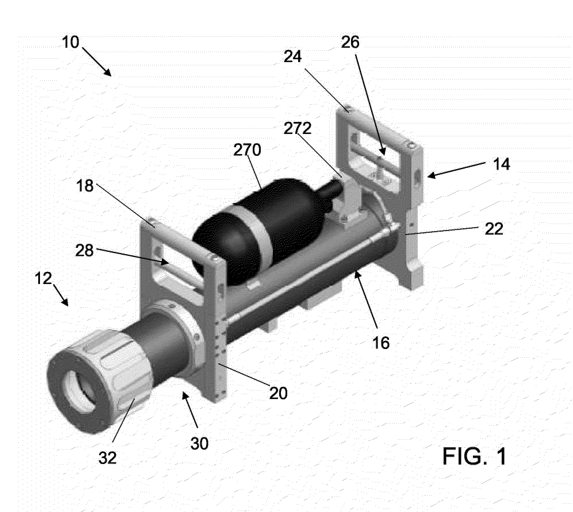
[0015]As shown in FIG. 1, there is provided a hand-held impact device 10 in accordance with one embodiment of the present invention. The device 10 includes a front end 12 and a rear end 14 with a substantially cylindrical-shaped core section 16. Front main block 20 is positioned axially inwardly along the core 16 from the front end 12, and includes a front handle 18. Rear main block 22 is positioned at or near the rear end 14 of the device, and includes a rear handle 24. A rear charge valve handle 26 and a front charge valve handle 28 are also shown. The front end includes a striker sub-assembly 30 having a striker head 32.

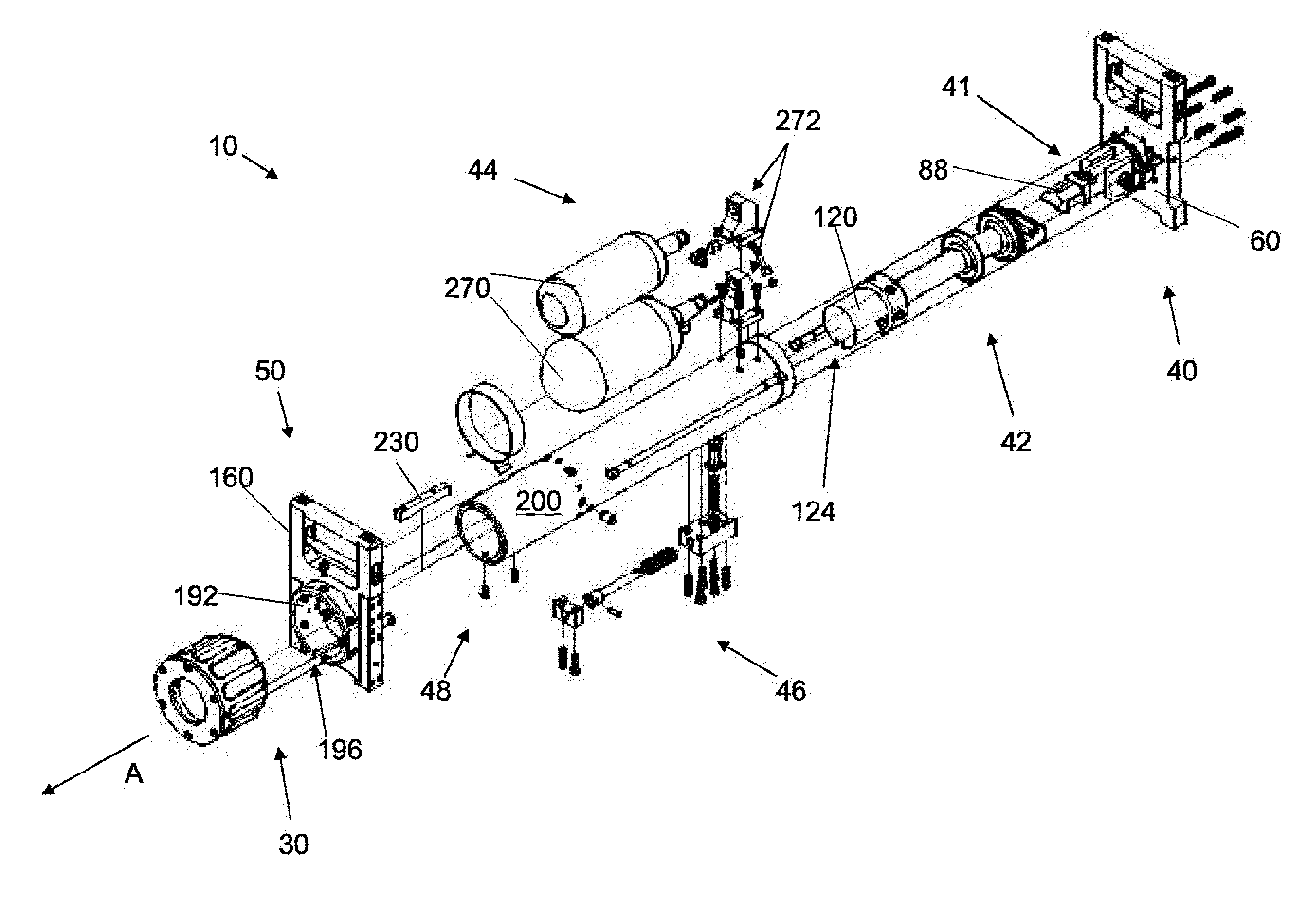
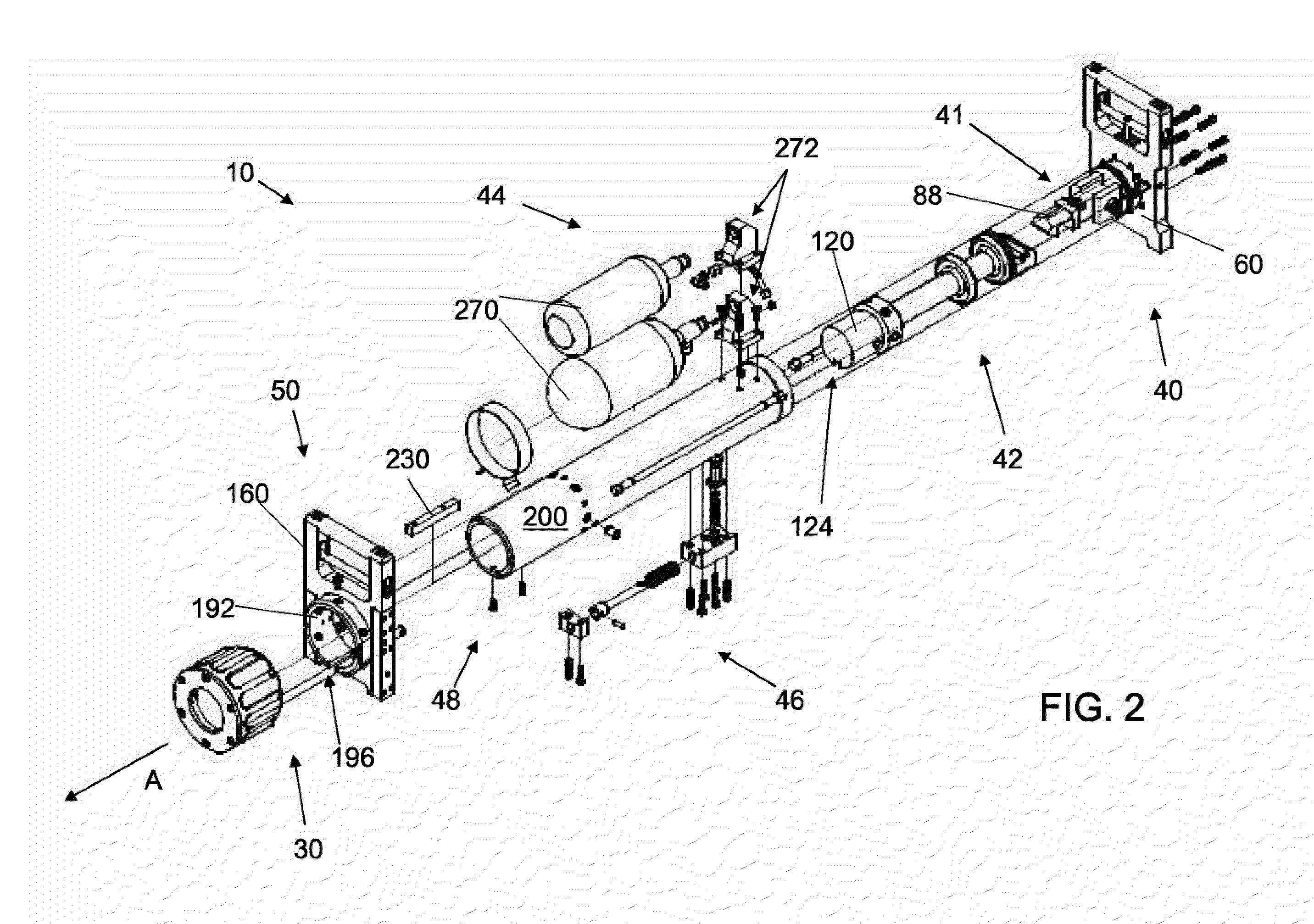
[0016]As shown in FIG. 2, several sub-assemblies combine to form the displayed embodiment of the device 10 of the present invention, including rear block sub-assembly 40, sear arm sub-assembly 41, piston sub-assembly 42, pressurization sub-assembly 44, sear trigger sub-assembly 46, core sub-assembly 48, front block sub-assembly 50 and striker sub-assembly 30.

[0017...


PUM

PropertyMeasurementUnit
lengthaaaaaaaaaa
velocityaaaaaaaaaa
pressureaaaaaaaaaa

Abstract

A pneumatic impact device and method provide a high powered striking force against a target object. The device includes a core shell that houses a piston sub-assembly and a sear arm sub-assembly, and that further defines a forward gas chamber and a rearward gas chamber. The rearward gas chamber is loaded with compressed fluid via a handle actuator. A mostly external sear trigger assembly responds to the impact of a striker plate against the target object, thereby releasing a sear arm that then releases a piston, which is then accelerated forward by the compressed fluid charge. The device can be re-set manually via compressed fluid (e.g., air) in one embodiment, or automatically via a spring mechanism in another embodiment.

Description

FIELD OF THE INVENTION[0001]The present invention relates to hand-held impact devices, and more particularly to a pneumatic hand-held impact device capable of use as a door breaching tool, and associated method.BACKGROUND OF THE INVENTION[0002]Battering rams are used by firefighters and police officers in order to quickly gain access through locked or barricaded doorways in buildings. Past battering rams are described, for example, in U.S. Pat. No. 5,329,685 to Gillespie. Battering rams generally suffer from being too heavy to operate and failing to provide enough power to break open a door on the first shot.[0003]Pneumatic devices, such as the device described in the Gillespie patent, can provide a higher striking velocity and thus a higher peak force that assists in breaking through a door on the first swing. However, such designs suffer from several disadvantages. First, the supply of compressed air is located internally and is therefore not rapidly interchangeable. Second, the s...

Claims


Application Information

Patent Timeline
Patent Type & Authority Applications(United States)
IPC IPC(8): A62B3/00B25D9/02B23P17/00
CPCA62B3/005Y10T29/494Y10T29/54Y10T29/5383Y10T29/49826B25D9/02B25D9/08
Inventor CHAMBERS, SCOTT E.RAHIM, RICK
Owner RAPID ENTRY SOLUTIONS
Why Eureka
Try Eureka