Energy absorption structure optimization method taking expected force response process as target

An energy-absorbing structure and optimization method technology, applied in the field of traffic safety, can solve problems such as reducing the amount of calculation, affecting the optimization results, and poor accuracy of the dynamic analysis results.

Active Publication Date: 2021-01-08
NORTHWESTERN POLYTECHNICAL UNIV
View PDF6 Cites 1 Cited by
  • Summary
  • Abstract
  • Description
  • Claims
  • Application Information

AI Technical Summary

Problems solved by technology

One is the equivalent static load method proposed in the article "Technical overview of the equivalent static loads method for non-linear static response structural optimization" published in "Structural and Multidisciplinary Optimization" by Gyung-Jin Park, which effectively reduces the amount of calculation. It is possible to use traditional optimization methods, but it is difficult for multiple static loads to be equivalent to the actual impact load conditions, and the accuracy of dynamic analysis results is poor, which affects the optimization results
The second is the hybrid cellular automata method for structural crashworthiness design in the article "Topometry optimization for crashworthiness design using hybrid cellular automata" published by Andrés Tovar in "International Journal of Vehicle Design". This method uses display dynamics analysis, The analysis results are accurate, but the "energy uniform distribution criterion" adopted is irrational, and the "area energy uniform distribution criterion" is too dependent on human prior experience, and the optimization results are uncertain

Method used


Image

  • Energy absorption structure optimization method taking expected force response process as target
  • Energy absorption structure optimization method taking expected force response process as target
  • Energy absorption structure optimization method taking expected force response process as target

Examples


Embodiment 1

[0085] This embodiment is an energy-absorbing structure optimization method targeting the expected force response history, and the specific process is:

[0086] Step 1, establish the original finite element model of the thin-walled pipe under impact:

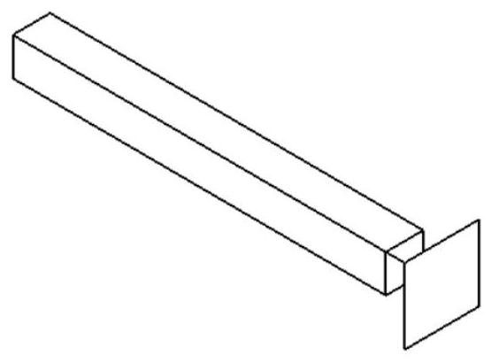
[0087] According to the structural characteristics of the impacted thin-walled tube and the rigid impact plate, the original finite element model of the thin-walled tube under impact is established. Such as figure 1 As shown, the structural characteristics of the impacted thin-walled tube and the rigid impact plate are divided into two parts, one part is a thin-walled tube with a square cross section, the side length of the thin-walled tube is 100 mm, the length is 1000 mm, and the wall thickness is 3.0 mm; the other part is a square rigid impact plate with a side length of 200mm. The rigid impingement plate is located at one end face of the thin-walled tube, and the center line in the length direction of the thin-walled tube ...

Embodiment 2

[0139] This embodiment is an energy-absorbing structure optimization method targeting the expected force response history, and the specific process is:

[0140] Step 1, establish the original finite element model of the thin-walled pipe under impact:

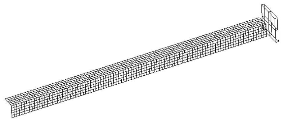
[0141] According to the structural characteristics of the impacted thin-walled tube and the rigid impact plate, the original finite element model of the thin-walled tube under impact is established. Such as Figure 8 and Figure 9 As shown, the structural characteristics of the impacted thin-walled tube and the rigid impact plate are divided into two parts, one part is a thin-walled tube with a square cross section, the side length of the thin-walled tube is 100 mm, the length is 1000 mm, and the wall thickness is 3.0 mm; the other part is a rectangular rigid impact plate located at one end of the thin-walled tube, the impact plate is 880mm long and 400mm wide.

[0142] The thin-walled tube is located at one end of the rigid ...

Embodiment 3

[0190] This embodiment is an energy-absorbing structure optimization method targeting the expected force response history, and the specific process is:

[0191] Step 1, establish the original finite element model of the thin-walled pipe under impact:

[0192] According to the structural characteristics of the impacted thin-walled tube and the rigid impact plate, the original finite element model of the thin-walled tube under impact is established. like Figure 8 and Figure 9 As shown, the structural characteristics of the impacted thin-walled tube and the rigid impact plate are divided into two parts, one part is a thin-walled tube with a square cross section, the side length of the thin-walled tube is 100 mm, the length is 1000 mm, and the wall thickness is 3.0 mm; the other part is a rectangular rigid impact plate located at one end of the thin-walled tube, the impact plate is 880mm long and 400mm wide.

[0193] The thin-walled tube is located at one end of the rigid imp...


PUM


Abstract

The invention discloses an energy absorption structure optimization method taking an expected force response process as a target, and the method comprises the steps: setting a proper expected force response curve, continuously updating the value of a target function in an optimization process in an iteration mode so as to obtain a new finite element model, and enabling an actual force response curve of a structure to be gradually close to the expected force response curve. And the energy absorption capacity of the structure is improved. According to the method, the deformation mode of the thin-walled tube can be changed, low-energy-absorption Euler deformation is changed into high-energy-absorption progressive buckling deformation, and multiple energy absorption evaluation indexes can be improved at the same time. The optimized actual force response curve of the thin-walled tube is closer to the expected force response curve. The energy absorption component obtained through the methodcan generate an ideal deformation mode, more impact kinetic energy is dissipated, and great guiding significance is achieved for design of energy absorption devices of various vehicles.

Description

technical field [0001] The invention belongs to the technical field of traffic safety, and in particular relates to an energy-absorbing structure optimization method aiming at an expected force response course. Background technique [0002] Safety is the most basic requirement in the design process of vehicles. In recent years, with the development of the transportation industry, collision accidents have become a prominent problem affecting the safety of passengers. Thin-walled metal structures are widely used in energy-absorbing structures in the automotive and aerospace industries due to their light weight, manufacturability, and good impact resistance. When a vehicle or aircraft collides, the energy-absorbing structure absorbs the impact energy through plastic deformation to maximize the safety of the occupants. The energy absorption capacity of thin-walled metal structures is closely related to its deformation mode. The ideal deformation mode is progressive buckling, w...

Claims


Application Information

Patent Timeline
Patent Type & Authority Applications(China)
IPC IPC(8): G06F30/23G06F30/15G06F30/17G06F111/06G06F119/14
CPCG06F30/23G06F30/15G06F30/17G06F2119/14G06F2111/06
Inventor 安伟刚王世根韩煦
Owner NORTHWESTERN POLYTECHNICAL UNIV
Why Eureka
Try Eureka